HP 100B Maintenance & Service Guide HP 100B All-in-One - Page 68
Inverter Board
 |
View all HP 100B manuals
Add to My Manuals
Save this manual to your list of manuals |
Page 68 highlights
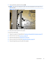
Inverter Board Description Inverter for use with Samsung/CMI display panels Inverter for use with LG display panels Inverter board cable Spare part number 646796-001 646797-001 646788-001 The inverter board is located on the left side of the computer under the optical drive. You must remove the optical drive and the optical drive bracket to gain access to the inverter board. The inverter board is secured with two screws and has three connectors. Figure 6-41 Inverter board location To remove the inverter board: 1. Prepare the computer for disassembly (see Preparing to Disassemble the Computer on page 29). 2. Remove the rear cover (see Rear Cover on page 30). 3. Remove the optical drive (see Optical Drive on page 36). 4. Remove the optical drive bracket (see Optical Drive Bracket on page 59). 5. Remove the two Torx T15M3.0x6.0 screws (1) that secure the board to the computer. 60 Chapter 6 Removal and Replacement Procedures All-in One (AIO) Chassis
-
 1
1 -
2
-
3
-
4
-
5
-
6
-
7
-
8
-
9
-
10
-
11
-
12
-
13
-
14
-
15
-
16
-
17
-
18
-
19
-
20
-
21
-
22
-
23
-
24
-
25
-
26
-
27
-
28
-
29
-
30
-
31
-
32
-
33
-
34
-
35
-
36
-
37
-
38
-
39
-
40
-
41
-
42
-
43
-
44
-
45
-
46
-
47
-
48
-
49
-
50
-
51
-
52
-
53
-
54
-
55
-
56
-
57
-
58
-
59
-
60
-
61
-
62
-
 63
63 -
 64
64 -
 65
65 -
 66
66 -
 67
67 -
 68
68 -
 69
69 -
 70
70 -
 71
71 -
 72
72 -
 73
73 -
74
-
75
-
76
-
77
-
78
-
79
-
80
-
81
-
82
-
83
-
84
-
85
-
86
-
87
-
88
-
89
-
90
-
91
-
92
-
93
-
94
-
95
-
96
-
97
-
98
-
99
-
100
-
101
-
102
-
103
-
104
 |
 |
