HP 8/8 Brocade Access Gateway Administrator's Guide v6.3.0 (53-1001345-01, Jul - Page 30
Access Gateway mapping
 |
View all HP 8/8 manuals
Add to My Manuals
Save this manual to your list of manuals |
Page 30 highlights
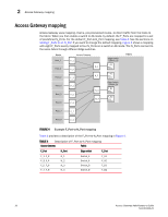
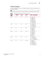
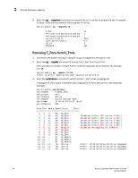
2 Access Gateway mapping Access Gateway mapping Access Gateway uses mapping-that is, pre-provisioned routes-to direct traffic from the hosts to the fabric. When you first enable a switch to AG mode, by default, the F_Ports are mapped to a set of predefined N_Ports. For the default F_Port-to-N_Port mapping, see Table 4. See the sections on Adding F_Ports to an N_Port if you want to change the default mapping. Figure 4 shows a mapping with eight F_Ports evenly mapped to four N_Ports on a switch in AG mode. The N_Ports connect to the same fabric through different Edge switches. Hosts Host_1 Host_2 Host_3 Access Gateway F_1 N_1 F_2 N_2 F_3 Edge Switch (Switch_A) F_A1 NPIV enabled F_A2 NPIV enabled Fabric Host_4 F_4 Host_5 F_5 Host_6 F_6 N_3 N_4 Edge Switch (Switch_B) F_B1 NPIV enabled F_B2 NPIV enabled Host_7 F_7 Host_8 F_8 FIGURE 4 Example F_Port-to-N_Port mapping Table 4 provides a description of the F_Port-to-N_Port mapping in Figure 4. TABLE 4 Description of F_Port-to-N_Port mapping Access Gateway Fabric F_Port N_Port Edge switch F_Port F_1, F_2 N_1 F_3, F_4 N_2 F_5, F_6 N_3 F_7, F_8 N_4 Switch_A Switch_A Switch_B Switch_B F_A1 F_A2 F_B1 F_B2 10 Access Gateway Administrator's Guide 53-1001345-01
-
 1
1 -
2
-
3
-
4
-
5
-
6
-
7
-
8
-
9
-
10
-
11
-
12
-
13
-
14
-
15
-
16
-
17
-
18
-
19
-
20
-
21
-
22
-
23
-
24
-
 25
25 -
 26
26 -
 27
27 -
 28
28 -
 29
29 -
 30
30 -
 31
31 -
 32
32 -
 33
33 -
 34
34 -
 35
35 -
36
-
37
-
38
-
39
-
40
-
41
-
42
-
43
-
44
-
45
-
46
-
47
-
48
-
49
-
50
-
51
-
52
-
53
-
54
-
55
-
56
-
57
-
58
-
59
-
60
-
61
-
62
-
63
-
64
-
65
-
66
-
67
-
68
-
69
-
70
-
71
-
72
-
73
-
74
-
75
-
76
-
77
-
78
-
79
-
80
-
81
-
82
 |
 |
