HP J4865A User Manual
HP J4865A Manual
 |
View all HP J4865A manuals
Add to My Manuals
Save this manual to your list of manuals |
HP J4865A manual content summary:
- HP J4865A | User Manual - Page 1
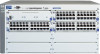
installation and getting started guide hp procurve series 4100gl switches www.hp.com/go/hpprocurve - HP J4865A | User Manual - Page 2
- HP J4865A | User Manual - Page 3
HP ProCurve Series 4100gl Switches Installation and Getting Started Guide - HP J4865A | User Manual - Page 4
software on equipment that is not furnished by Hewlett-Packard. Warranty See the Customer Support/Warranty booklet included with the product. A copy of the specific warranty terms applicable to your Hewlett-Packard products and replacement parts can be obtained from your HP Sales and Service Office - HP J4865A | User Manual - Page 5
Introducing the HP ProCurve Series 4100gl Switches Front of the Switch 1-4 LEDs 1-5 LED Mode Select Button and Indicator LEDs 1-7 Console Port 1-8 Reset Button 1-8 Clear Button 1-8 Back of the Switch 1-9 Power Connector 1-9 Slot for Redundant Power Supply 1-9 Switch Features 1-10 - HP J4865A | User Manual - Page 6
Switch LEDs 4-10 Checking Console Messages 4-10 Testing Twisted-Pair Cabling 4-11 Testing Switch-to-Device Network Communications 4-11 Testing End-to-End Network Communications 4-11 Restoring the Factory Default Configuration 4-12 Downloading New Code 4-13 HP Customer Support Services - HP J4865A | User Manual - Page 7
Before Calling Support 4-13 A Specifications Physical A-1 Electrical A-1 Environmental A-2 Acoustic A-3 Switch 4108gl and Bundle; 4160gl A-3 Switch 4104gl, 4148gl, and 4140gl A-3 Network Connectors A-3 Safety A-3 B Switch Ports and Network Cables Switch Ports B-1 Twisted Pair - HP J4865A | User Manual - Page 8
Consideraciones sobre seguridad C-5 Safety Information (Japan C-6 Safety Information (China C-7 EMC Regulatory Statements C-8 U.S.A C-8 Canada C-8 Australia/New Zealand C-8 Japan C-8 Korea C-9 Taiwan C-9 Regulatory Model Identification Number C-9 Index - HP J4865A | User Manual - Page 9
overview Switch 4104gl and Switch 4148gl. The Switch 4104gl is available as an open 4-slot chassis (J4887A) or as the Switch 4148gl (J4888A) with two 24port 10/100-TX gl Modules pre-installed. HP ProCurve Switch4104gl (J4887A) � � � HP ProCurve Switch - HP J4865A | User Manual - Page 10
is available as an open 8-slot chassis (J4865A) or as the Switch 4108gl Bundle (J4861A) with one 3-port Gigabit Transceiver gl Module and three 24-port 10/100-TX gl Modules pre-installed. HP ProCurve Switch4108gl (J4865A) HP ProCurve Switch 4108gl Bundle (J4861A) with one Gigabit Transceiver gl - HP J4865A | User Manual - Page 11
Introducing the HP ProCurve Series 4100gl Switches Introducing the HP ProCurve Series 4100gl Switches Switch 4140gl. The Switch 4140gl is available as a four slot chassis (J8151A) with two 20-port Gig-T gl modules with 2 mini-GBIC Gig ports (J4908A) preinstalled. - HP J4865A | User Manual - Page 12
Introducing the HP ProCurve Series 4100gl Switches Introducing the HP ProCurve Series 4100gl Switches Front of the Switch Front of the Switch Console Port Power and Fault LEDs Reset and Clear buttons Status LEDs for the Fans, Power Supplies, and Switch Modules LED Mode Select button and - HP J4865A | User Manual - Page 13
green numbers corresponding to the power supply positions) On Off Flashing† Meaning The switch is receiving power. The switch is NOT receiving power. The normal state; indicates that there are no fault conditions on the switch. A fault has occurred on the switch, one of the switch modules, a power - HP J4865A | User Manual - Page 14
Introducing the HP ProCurve Series 4100gl Switches Introducing the HP ProCurve Series 4100gl Switches Front of the Switch LEDs State Meaning Status/ On Modules (green - letters corresponding to the switch Off module slots) Flashing† A module is installed in the switch module slot - HP J4865A | User Manual - Page 15
Introducing the HP ProCurve Series 4100gl Switches Introducing the HP ProCurve Series 4100gl Switches Front of the Switch LED Mode Select Button and Indicator LEDs To optimize the amount of information that can be displayed for each of the switch ports, the Series 4100gl Switches use a Mode LED for - HP J4865A | User Manual - Page 16
as HP ProCurve Manager for Hubs & Switches. Press the Reset button also after changing the module type that is installed in any of the switch module slots while the switch is powered on. In this case, the switch must be reset to initialize the new module type. See "Hot Swapping Switch Modules" on - HP J4865A | User Manual - Page 17
HP ProCurve Series 4100gl Switches Introducing the HP ProCurve Series 4100gl Switches Back of the Switch Back of the Switch . AC power connector slot for installing optional redundant power supply Caution Power Connector The Series 4100gl Switches do not have a power switch; they are powered - HP J4865A | User Manual - Page 18
combination and can be "hot swapped". ■ the supported HP ProCurve transceivers can be hot swapped into the Gigabit Transceiver gl Module. ■ the supported mini-GBICs can be hot swapped into the mini-GBIC gl Module. ■ high performance -- 36.6 Gbps switching fabric. ■ plug-and-play networking-all ports - HP J4865A | User Manual - Page 19
through an intuitive menu interface. • HP ProCurve Manager for Hubs & Switches-an SNMP-based graphical interface that is used to manage your entire network, included with your new switch. • Supported by HP OpenView ProCurve Network Manager-an HP OpenView application that accurately displays your - HP J4865A | User Manual - Page 20
- This page is intentionally unused. - - HP J4865A | User Manual - Page 21
and Getting Started Guide, and other related documentation) ■ HP ProCurve Manager for Hubs & Switches - CD ROM and booklet ■ Customer Support/Warranty booklet ■ Accessory kit (5065-6521 for the 8-slot Switch 4108gl and Switch 4108gl Bundle; 5064-9943 for the 4-slot Switch 4104gl and Switch 4148gl - HP J4865A | User Manual - Page 22
so they can also be installed and removed after the switch is powered on. Note: Make sure you use only HP ProCurve Switch gl Modules in your Series 4100gl Switches. 3. (Optional) Install second power supply (page 2-9). The Series 4100gl Switches have a slot in the back for installing a second, load - HP J4865A | User Manual - Page 23
your HP Series 4100gl Switch: ■ switch power supply slot. A cover plate is required for safe operation, and to ensure proper switch cooling. ■ To avoid energy and mechanical hazards, never allow any part of your body, jewelry, tool, or other foreign object to enter any module or power supply - HP J4865A | User Manual - Page 24
properly grounded, then use the power cord supplied with the switch to connect it to the power source. If your installation requires a different power cord than the one supplied with the switch and power supply, be sure the cord is adequately sized for the switch's current requirements. In addition - HP J4865A | User Manual - Page 25
specifications. See the following table for cable types and lengths, and see appendix B, "Cables and Connectors" for more information: Table 2-1. Summary of Cable Types to Use With the Switch 100 meters Note: The Switch 2800 Series devices are end nodes, such as computers, or to other switches - HP J4865A | User Manual - Page 26
may be needed - See the Installation Guide that came with your module for more information. Gigabit-LH (on Gigabit-LH-LC mini-GBIC) The same single-mode fiber-optic cables as for • 70 kilometers Gigabit-LX. Note: Gigabit-LH - Between the transmit and receive ends of the cable, at least 5db of - HP J4865A | User Manual - Page 27
details, see the instructions in the manual that comes with the module. Ensure you install only HP ProCurve Switch gl Modules. Switch xl Modules will fit into your Switch gl slots, but they will not operate. Avoid any electrostatic discharge problems by handling the modules only by their bulkheads - HP J4865A | User Manual - Page 28
Installing the Series 4100gl Switches Installation Procedures 1. Insert module into the guides and slide it in until it is fully inserted. "Low-force" connector. High insertion force is not needed and should not be used. Installing the Series 4100gl Switches The module is fully inserted when the - HP J4865A | User Manual - Page 29
For safety and proper switch cooling, if either of the power supply slots are not being used, make sure to attach the cover plate over the slot. Please see the Installation Precautions on page 2-3 for more information. For installation details, see the instructions in the manual that comes with the - HP J4865A | User Manual - Page 30
into the opening, then slide it all the way in until it connects to the switch. The power supply face plate will be flush with the back face of the switch. Once the power supply is installed, make sure you tighten the four retaining screws that hold it in place. The screws can be tightened with - HP J4865A | User Manual - Page 31
Passes Self Test After you have installed any modules and the optional second power supply, but before mounting the switch in its network location, you should first verify that it is working properly by plugging it into a power source and verifying that it passes its self test. If you have installed - HP J4865A | User Manual - Page 32
number and type of modules installed in the switch. LED Behavior: During the self test: ■ Initially, Power and Fault, and all the switch Power LED stays on, and the Status LEDs on the switch chassis stay on for the devices installed: one for each switch module installed, one for each power supply - HP J4865A | User Manual - Page 33
the mode selected. In the default mode (Activity), the Mode LEDs should flicker showing network activity on the port. • For the ports that are not connected to active network devices, the LEDs will stay off. 5. Mount the Switch After the modules and optional power supply are installed and you have - HP J4865A | User Manual - Page 34
Installing the Series 4100gl Switches Installing the Series 4100gl Switches Installation Procedures Attaching brackets to the 4-slot switches. 10 mm M4 screws Attaching brackets to the 8-slot switches. 10 mm M4 screws 2-14 - HP J4865A | User Manual - Page 35
the Series 4100gl Switches Installing the Series 4100gl Switches Installation Procedures 2. Partially install a screw (5/8-inch number 12-24) into a close (0.5-inch) pair on both sides of the rack . 3. Place the switch in the rack and lower it so the notches in the bottom of the bracket slide - HP J4865A | User Manual - Page 36
or other horizontal surface. Use a sturdy surface in an uncluttered area. You may want to secure the networking cables and switch power cord to the table legs or other part of the surface structure to help prevent people from tripping over the cords. Ensure the air flow is not restricted around the - HP J4865A | User Manual - Page 37
supplied with the switch allow you to mount it on a wall. The illustrations below show mounting a Switch 4108gl. The Switch 4104gl and 4148gl would be mounted in a similar way. For safe operation, do not install the switch with the vents or fans facing downward. The only recommended and supported - HP J4865A | User Manual - Page 38
a redundant power supply module into the switch, it should be connected to a separate AC power source. Then, if there is a power outage from one of the AC sources, the switch will continue to operate by power coming from the other source. See the HP ProCurve Switch gl/xl RPS Installation Guide for - HP J4865A | User Manual - Page 39
in troubleshooting ■ Download new software to the switch ■ Add passwords and other security features to control access to the switch from switch with an IP address and subnet mask by using either out-of-band console access or through DHCP/Bootp. The Series 410gl Switches can simultaneously support - HP J4865A | User Manual - Page 40
has a 25- pin serial connector, first attach a 9-pin to 25-pin straight-through adapter to the PC end of the console cable.) 2. Turn on the terminal or console cable supplied with the switch PC's power and, if using a PC, start the PC terminal program. 3. Press two or three times and you - HP J4865A | User Manual - Page 41
in the power cord (power cycle). If two power supplies are installed, both power cords would have to be unplugged. ■ issuing the reboot system command from the switch console CLI, or selecting the Reset or Reboot option from the switch console menu, the web browser interface, or HP ProCurve Manager - HP J4865A | User Manual - Page 42
, as shown in the above illustration. Notice the end node devices are connected to the switch by either straightthrough or crossover twisted-pair cables. Either cable type can be used because of the "HP Auto-MDIX" feature on the 10/100-TX gl Modules and the standard "Auto MDI/MDI-X" feature on - HP J4865A | User Manual - Page 43
through either the Gigabit Transceiver gl Module or the 100/1000-T gl Module, the Series 4100gl Switches can provide that access beyond the edge for a high number of network users. In the above illustration, two Switch 4108gls are connected to an HP ProCurve Routing Switch 9308, which can serve as - HP J4865A | User Manual - Page 44
management includes Telnet access and web browser interface access to the Commander and to each Member switch through the Commander. For more information on stacking your Series 4100gl Switches, please see the Management and Configuration Guide that is on the documentation CD-ROM that came with your - HP J4865A | User Manual - Page 45
the SNMP manage ment tool, HP ProCurve Manager for Hubs & Switches, please see the Manage ment and Configuration Guide on the documentation CD-ROM that came with your switch. Recommended Minimal Configuration In the factory default configuration, the switch has no IP (Internet Protocol) address - HP J4865A | User Manual - Page 46
switch model number: HP Procurve Switch 4104GL# 2. At the prompt, enter the setup command to display the Switch Setup screen. The following illustration shows the Setup screen with the default settings. Getting Started With Switch Configuration 3. Use the ïï ïïïkey to select the Manager Password - HP J4865A | User Manual - Page 47
Guide that is on the documentation CD-ROM that came with your switch: Parameter Default Password blank Recommended; up to 16 characters (no blank spaces) Logon Default CLI The default switch uses to acquire a time signal. The options are SNTP and TimeP. IP Config DHCP/Bootp Set to Manual - HP J4865A | User Manual - Page 48
SNMP-based network manage ment tool such as HP ProCurve Manager for Hubs & Switches. To Recover from a Lost Manager Password: If you cannot start a console session at on the Series 4100gl Switches, please see the Management and Configuration Guide that is on the documentation CD-ROM that came - HP J4865A | User Manual - Page 49
a key, and you will then see the switch console command (CLI) prompt, for example: HP Procurve Switch 4108GL# Enter help or ? to see a switch's IP address as the URL. No additional software installation is required to make this interface available; it is included in the switch's onboard software - HP J4865A | User Manual - Page 50
and Configuration Guide that is on the documentation CDROM that came with your switch. An extensive help system is also available for the web browser interface. To access the help system though, the subnet on which the switch is installed must have access to the internet, or HP ProCurve Manager for - HP J4865A | User Manual - Page 51
tools (page 4-9) ■ hardware diagnostic tests (page 4-10) ■ restoring the factory default configuration (page 4-12) ■ downloading new code (page 4-13) ■ HP Customer Support Services (page 4-13) Basic Troubleshooting Tips Most problems are caused by the following situations. Check for these items - HP J4865A | User Manual - Page 52
, the web browser interface, or HP ProCurve Manager for Hubs and Switches. The Series 4100gl Switches also support Trunking, which allows multiple network cables to be used for a single network connection without causing a data path loop. See the Management and Configuration Guide that is on the - HP J4865A | User Manual - Page 53
software. Use the switch console to switch for more information. For more information on possible network problems and their solutions, refer to the technical note "Troubleshooting LAN Performance and Intermittent Connectivity Problems", which can be found on the HP ProCurve web site, http://www.hp - HP J4865A | User Manual - Page 54
that you see on your switch 2. Refer to the corresponding diagnostic tip on the next few pages. Table 4-1. LED Error Indicators LED Pattern Indicating Problems Diagnostic Tips Power Fault Self Test Module Status (one LED per module) Power Status (one LED per power supply) Fan Status Port Link - HP J4865A | User Manual - Page 55
the module without having to power down the switch. Call your HP-authorized LAN dealer, or use the electronic support services from HP to get information on supported Switch gl modules. The modules that are available as of the printing of this manual are listed on page 1-10. Troubleshooting - HP J4865A | User Manual - Page 56
installed module, and the switch has You can reset the switch by any of these methods: • pressing the Reset button. • power cycling the switch. not yet been reset. • selecting the reset or reboot option from the console, web browser interface, or HP ProCurve Manager. Troubleshooting 4-6 - HP J4865A | User Manual - Page 57
number. Reconnect the power supply to the AC power source. If the error indication reoccurs after the supply is reinstalled, the power supply may be faulty. Call your HP- authorized LAN dealer, or use the electronic support services from HP to get assistance. See the Customer Support/Warranty - HP J4865A | User Manual - Page 58
Troubleshooting Diagnosing with the LEDs Tip Number Problem The network connection is not working properly. Solution Try the following procedures: • For the indicated port, verify that both ends of the cabling, at the switch and the connected device, are securely connected. • Verify the connected - HP J4865A | User Manual - Page 59
these proactive networking features: ■ HP ProCurve Manager for Hubs & Switches - an SNMP-based network management tool that is included with your switch ■ A graphical web browser interface that you can use to manage your switch from a PC that is running a supported web browser, for example Microsoft - HP J4865A | User Manual - Page 60
go off after approximately 90 to 150 seconds depending on the number and type of modules installed in the switch. If these LEDs stay on longer than 180 seconds or begin flashing, the switch, or a module, or an individual mini-GBIC or transceiver may have to be replaced as indicated by the LEDs - HP J4865A | User Manual - Page 61
Configuration Guide that is on the documentation CD-ROM that came with your switch for more information. These tests can also be performed from an SNMP network management station running a program that can manage the switch, for example, HP ProCurve Manager for Hubs & Switches. Testing End-to-End - HP J4865A | User Manual - Page 62
the Factory Default Configuration As part of your troubleshooting process, it may become necessary to return the switch configuration to the factory default settings. This process momen tarily interrupts the switch operation, clears any passwords, clears the console event log, resets the network - HP J4865A | User Manual - Page 63
the HP ProCurve web site, http://www.hp.com/go/hpprocurve. HP Customer Support Services If you are still having trouble with your switch, Hewlett-Packard offers support 24 hours a day, seven days a week through the use of a number of automated electronic services. See the Customer Support/Warranty - HP J4865A | User Manual - Page 64
- This page is intentionally unused. - - HP J4865A | User Manual - Page 65
Specifications A Specifications Physical Width: Depth: Height: • Switch 4108gl and Bundle; 4160gl • Switch 4104gl, 4148gl, and 4140gl Weight: • Switch 4108gl • Switch 4108gl Bundle • Switch 4160gl 44.2 cm (17.2 in) 39.0 cm (15.2 in) • 22.5 cm (8.7 in) • 13.5 cm (5.2 in) • 11.6 kg (25.5 lbs) • 13 - HP J4865A | User Manual - Page 66
Specifications Environmental Temperature: Relative humidity: (non-condensing) Maximum altitude: Operating 0°C to 55°C (32°F to 131°F) 15% to 95% at 40°C (104°F) Non-Operating -40°C to 70°C (-40°F to 158°F) 15% to 90% at 65°C (149°F) 4.6 Km (15,000 ft) 4.6 Km (15,000 ft) Specifications A-2 - HP J4865A | User Manual - Page 67
Specifications Running H/F 1 Acoustic Switch 4108gl and Bundle; 4160gl: Geräuschemission LwA=53.0 dB am fiktiven Arbeitsplatz nach DIN 45635 T.19 Noise Emission LwA=53.0 dB in a virtual workspace according to DIN 45635 T.19 Switch 4104gl on the 100/1000-T gl Module and the 100/1000-T Transceiver - HP J4865A | User Manual - Page 68
- This page is intentionally unused. - - HP J4865A | User Manual - Page 69
Switches, including minimum pin-out information and specifications for twisted-pair cables. Incorrectly wired cabling is the most common cause of problems for LAN communications. HP and the LCtype connector port on the Gigabit-LX LC mini-GBIC Transceiver transmit at 1300 nm wavelength, and accept the - HP J4865A | User Manual - Page 70
ohm differential UTP or STP cable, complying with IEEE 802.3u 100Base-TX specifications, fitted with RJ-45 connectors. 1000 Mbps Operation Category 5 100-ohm cabling, be sure to include the patch cables that connect the switch and other end devices to the patch panels on your site. The patch cables - HP J4865A | User Manual - Page 71
. LC - Gigabit-LX mini-GBIC SC - Gigabit-LX transceiver • single-mode cable: 10 kilometers • Multimode cable: 550 meters Note: To use multimode cables for Gigabit-LX, a mode conditioning patch cord may be needed - See the Installation Guide that came with your module for more information. 9/125 - HP J4865A | User Manual - Page 72
HP Auto-MDIX and the IEEE 802.3ab Auto MDI/ MDI-X are completely compatible. If you connect a Series 4100gl Switch twisted-pair port to another switch end nodes, use a straight-through cable; for connections to MDI-X ports, such as on hubs and other switches (STP) cable, as supported by the IEEE 802.3 - HP J4865A | User Manual - Page 73
-Pair Cable for 10 Mbps or 100 Mbps Network Connections Because of the HP Auto-MDIX operation of the 10/100 ports on the switches, for all network connections, to PCs, servers or other end nodes, or to hubs or other switches, you can use straight-through cables. If any of these ports are - HP J4865A | User Manual - Page 74
for 10 Mbps or 100 Mbps Network Connection The HP Auto-MDIX operation of the 10/100 ports on the switches also allows you to use crossover cables for all network connections, to PCs, servers or other end nodes, or to hubs or other switches. If any of these ports are given a fixed configuration - HP J4865A | User Manual - Page 75
-Through Twisted-Pair Cable for 1000 Mbps Network Connections 1000Base-T connections require that all four pairs or wires be connected. Cable Diagram Switch Ports and Network Cables Not e . Pins 1 and 2 on connector "A" must be wired as a twisted pair to pins 1 and 2 on connector "B". Pins 3 and - HP J4865A | User Manual - Page 76
- This page is intentionally unused. - - HP J4865A | User Manual - Page 77
of the network with caution. Servicing There are no user-serviceable parts inside these products. Any servicing, adjustment, maintenance, or repair must be performed only by service-trained personnel. These products do not have a power switch; they are powered on when the power cord is plugged in - HP J4865A | User Manual - Page 78
Safety and EMC Regulatory Statements Informations concernant la sécurité Informations concernant la sécurité ! WARNING CAUTION Symbole de référence à la documentation. Si le produit est marqué de ce symbole, reportez-vous à la documentation du produit afin d'obtenir des informations plus détaillé - HP J4865A | User Manual - Page 79
Safety and EMC Regulatory Statements Hinweise zur Sicherheit Hinweise zur Sicherheit ! WARNING CAUTION Symbol für Dokumentationsverweis. Wenn das Produkt mit diesem Symbol markiert ist, schlagen Sie bitte in der Produktdokumentation nach, um mehr Informationen über das Produkt zu erhalten. Symbol - HP J4865A | User Manual - Page 80
Safety and EMC Regulatory Statements Considerazioni sulla sicurezza Considerazioni sulla sicurezza ! WARNING CAUTION Simbolo di riferimento alla documentazione. Se il prodotto è contras segnato da questo simbolo, fare riferimento alla documentazione sul prodotto per ulteriori informazioni su di - HP J4865A | User Manual - Page 81
precaución los componentes de metal de la LAN que estén al descubierto. Este aparato no contiene pieza alguna susceptible de reparación por parte del usuario. Todas las reparaciones, ajustes o servicio de mantenimiento debe realizarlos sola mente el técnico. Este producto no tiene interruptor de - HP J4865A | User Manual - Page 82
Safety and EMC Regulatory Statements Safety Information (Japan) Safety Information (Japan) C-6 Safety and EMC Regulatory Statements - HP J4865A | User Manual - Page 83
Safety and EMC Regulatory Statements Safety Information (China) Safety Information (China) C-7 Safety and EMC Regulatory Statements - HP J4865A | User Manual - Page 84
comply with the limits for a Class A digital device, pursuant to Part 15 of the FCC Rules. These limits are designed to provide reasonable energy and, if not installed and used in accordance with the instruction manual, may cause interference to radio communications. Operation of this equipment in - HP J4865A | User Manual - Page 85
the HP ProCurve Series 4100gl Switches are assigned a Regulatory Model Number. The Regulatory Model Number for these switches is RSVLC-0201. This regulatory number should not be confused with the marketing name (HP ProCurve Series 4100gl Switches), or product numbers (J4861A, J4865A, J4887A, J4888A - HP J4865A | User Manual - Page 86
HP ProCurve Switch 4108gl Bundle, HP ProCurve Switch 4108gl, HP ProCurve Switch 4104gl, HP ProCurve Switch 4148gl (bundle) HP ProCurve Switch 4140gl (bundle) HP ProCurve Switch 4160gl (bundle) Model Number: J4861A, J4865A, J4887A, J4888A, J8151A, J8152A Accessories Packard Sales and Service Office - HP J4865A | User Manual - Page 87
used with ... B-2 twisted-pair cable specifications ... B-2 A Act LED ... 1-6 auto MDI/MDI-X operation ... B-5, B-7 HP Auto-MDIX feature ... B-3 B back of switch description ... 1-9 power connector ... 1-9 slot for redundant power supply ... 1-9 basic connectivity, example topology ... 2-22 - HP J4865A | User Manual - Page 88
... 3-3 IP address, manually ... 3-3 manager password ... 3-2 restoring factory defaults ... 1-8, 4-12 subnet mask ... 3-3 Switch Setup screen ... 3-2 connecting the switch to a power source ... 2-18 connector specifications ... A-3 console checking messages during troubleshooting ... 4-10 - HP J4865A | User Manual - Page 89
mini-GBICs ... 1-10 redundant power supply ... 1-9, 2-9 resetting the switch for new module type ... 2-21 switch modules ... 1-10, 2-21 transceivers ... 1-10 HP Auto-MDIX feature description ... B-3 I in-band console access, types of ... 2-19 managing the switch ... 3-1 included parts - HP J4865A | User Manual - Page 90
network cable ... B-6 mini-GBICs hot swap feature ... 1-10 indications of unsupported ... 4-7 supported types ... 1-10 Mode LEDs description ... 1-6 selecting the display ... 1-7 module hot swap feature ... 1-10 module slots location on switch ... 1-4 Module Status LEDs ... 1-6 showing - HP J4865A | User Manual - Page 91
mini-GBICs ... 1-10 supported switch modules ... 1-10 supported transceivers ... 1-10 switch connecting to a power source ... 2-18 description ... 1-1 electrical specifications ... A-1 environmental specifications ... A-2 features ... 1-10 front panel description ... 1-4 included parts - HP J4865A | User Manual - Page 92
11 Proactive Network tools ... 4-9 restoring factory default configuration ... 4-12 testing connections to other devices ... 4-11 testing end-to-end communications ... 4-11 testing the switch ... 4-10 testing the twisted-pair cables ... 4-11 unsupported mini-GBICs ... 4-7 twisted-pair cable - HP J4865A | User Manual - Page 93
- HP J4865A | User Manual - Page 94
-Packard Development Company, L.P. Reproduction, adaptation, or translation without prior written permission is prohibited except as allowed under the copyright laws. Printed in Singapore November 2003 Manual Part Number 5990-6048 *5990-6048*
-
 1
1 -
 2
2 -
 3
3 -
 4
4 -
 5
5 -
 6
6 -
 7
7 -
8
-
9
-
10
-
11
-
12
-
13
-
14
-
15
-
16
-
17
-
18
-
19
-
20
-
21
-
22
-
23
-
24
-
25
-
26
-
27
-
28
-
29
-
30
-
31
-
32
-
33
-
34
-
35
-
36
-
37
-
38
-
39
-
40
-
41
-
42
-
43
-
44
-
45
-
46
-
47
-
48
-
49
-
50
-
51
-
52
-
53
-
54
-
55
-
56
-
57
-
58
-
59
-
60
-
61
-
62
-
63
-
64
-
65
-
66
-
67
-
68
-
69
-
70
-
71
-
72
-
73
-
74
-
75
-
76
-
77
-
78
-
79
-
80
-
81
-
82
-
83
-
84
-
85
-
86
-
87
-
88
-
89
-
90
-
91
-
92
-
93
-
94
 |
 |

installation and
getting started guide
www.hp.com/go/hpprocurve
hp
procurve
series 4100gl switches