HP J4865A User Manual - Page 52
Improper Network Topologies., Spanning Tree Protocol, Trunking, no data path loops
 |
View all HP J4865A manuals
Add to My Manuals
Save this manual to your list of manuals |
Page 52 highlights
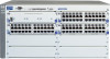
Troubleshooting Basic Troubleshooting Tips ■ Improper Network Topologies. It is important to make sure you have a valid network topology. Common topology faults include excessive cable length and excessive repeater delays between end nodes. If you have network problems after recent changes to the network, change back to the previous topology. If you no longer experience the problems, the new topology is probably at fault. Some basic sample topologies are shown at the end of chapter 2 in this manual. In addition, you should make sure that your network topology contains no data path loops. Between any two end nodes, there should be only one active cabling path at any time. Data path loops will cause broadcast storms that will severely impact your network performance. With your Series 4100gl Switches, if you wish to build redundant paths between important nodes in your network to provide some fault toler ance, you should enable Spanning Tree Protocol support on the switch. This ensures that only one of the redundant paths is active at any time, thus avoiding data path loops. Spanning Tree can be enabled through the switch console, the web browser interface, or HP ProCurve Manager for Hubs and Switches. The Series 4100gl Switches also support Trunking, which allows multiple network cables to be used for a single network connection without causing a data path loop. See the Management and Configuration Guide that is on the documentation CD-ROM that came with your switch for more information on Spanning Tree and on Trunking. • Trunking for the J4908A is accomplished differently than normal, therefore you must follow these guidelines. Looking at the J4908A physical port layout, it looks like this: 1 2 3456 7 8 9 10 11 12 13 14 15 16 21 17 18 19 20 22 The trunking grouping is as follows: Group1: 1-5, 7-11, 16 Group2: 6, 12-15, 17-22 Ports 21 and 22, which are the two Fiber links, are expected to be trunked together. The following graphic depicts the proper trunking. Troubleshooting 4-2
-
 1
1 -
2
-
3
-
4
-
5
-
6
-
7
-
8
-
9
-
10
-
11
-
12
-
13
-
14
-
15
-
16
-
17
-
18
-
19
-
20
-
21
-
22
-
23
-
24
-
25
-
26
-
27
-
28
-
29
-
30
-
31
-
32
-
33
-
34
-
35
-
36
-
37
-
38
-
39
-
40
-
41
-
42
-
43
-
44
-
45
-
46
-
 47
47 -
 48
48 -
 49
49 -
 50
50 -
 51
51 -
 52
52 -
 53
53 -
 54
54 -
 55
55 -
 56
56 -
 57
57 -
58
-
59
-
60
-
61
-
62
-
63
-
64
-
65
-
66
-
67
-
68
-
69
-
70
-
71
-
72
-
73
-
74
-
75
-
76
-
77
-
78
-
79
-
80
-
81
-
82
-
83
-
84
-
85
-
86
-
87
-
88
-
89
-
90
-
91
-
92
-
93
-
94
 |
 |
