HP J4865A User Manual - Page 37
Wall Mounting - 4108gl
 |
View all HP J4865A manuals
Add to My Manuals
Save this manual to your list of manuals |
Page 37 highlights
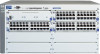
Caution Installing the Series 4100gl Switches Installation Procedures Wall Mounting The mounting brackets supplied with the switch allow you to mount it on a wall. The illustrations below show mounting a Switch 4108gl. The Switch 4104gl and 4148gl would be mounted in a similar way. For safe operation, do not install the switch with the vents or fans facing downward. The only recommended and supported wall mounting orientation is with the unit upright and the modules facing out, as shown in the illustra tions below. Additionally, the switch should be mounted only to a wall or wood surface that is at least 1/2-inch plywood or its equivalent. 1. Use a #1 Phillips (cross-head) screwdriver and attach the mounting brackets to the switch with the included 10-mm M4 screws. 10 mm M4 screws Installing the Series 4100gl Switches 2. Attach the switch to the wall or wood surface with four 5/8-inch number 12 wood screws or larger (not included). 5/8-inch number 12 wood screws 2-17
-
 1
1 -
2
-
3
-
4
-
5
-
6
-
7
-
8
-
9
-
10
-
11
-
12
-
13
-
14
-
15
-
16
-
17
-
18
-
19
-
20
-
21
-
22
-
23
-
24
-
25
-
26
-
27
-
28
-
29
-
30
-
31
-
 32
32 -
 33
33 -
 34
34 -
 35
35 -
 36
36 -
 37
37 -
 38
38 -
 39
39 -
 40
40 -
 41
41 -
 42
42 -
43
-
44
-
45
-
46
-
47
-
48
-
49
-
50
-
51
-
52
-
53
-
54
-
55
-
56
-
57
-
58
-
59
-
60
-
61
-
62
-
63
-
64
-
65
-
66
-
67
-
68
-
69
-
70
-
71
-
72
-
73
-
74
-
75
-
76
-
77
-
78
-
79
-
80
-
81
-
82
-
83
-
84
-
85
-
86
-
87
-
88
-
89
-
90
-
91
-
92
-
93
-
94
 |
 |
