HP Pavilion dm1-3000 HP Pavilion dm1 Notebook PC - Maintenance and Service Gui - Page 61
If it is necessary to replace the display bezel or any of the display assembly internal
 |
View all HP Pavilion dm1-3000 manuals
Add to My Manuals
Save this manual to your list of manuals |
Page 61 highlights
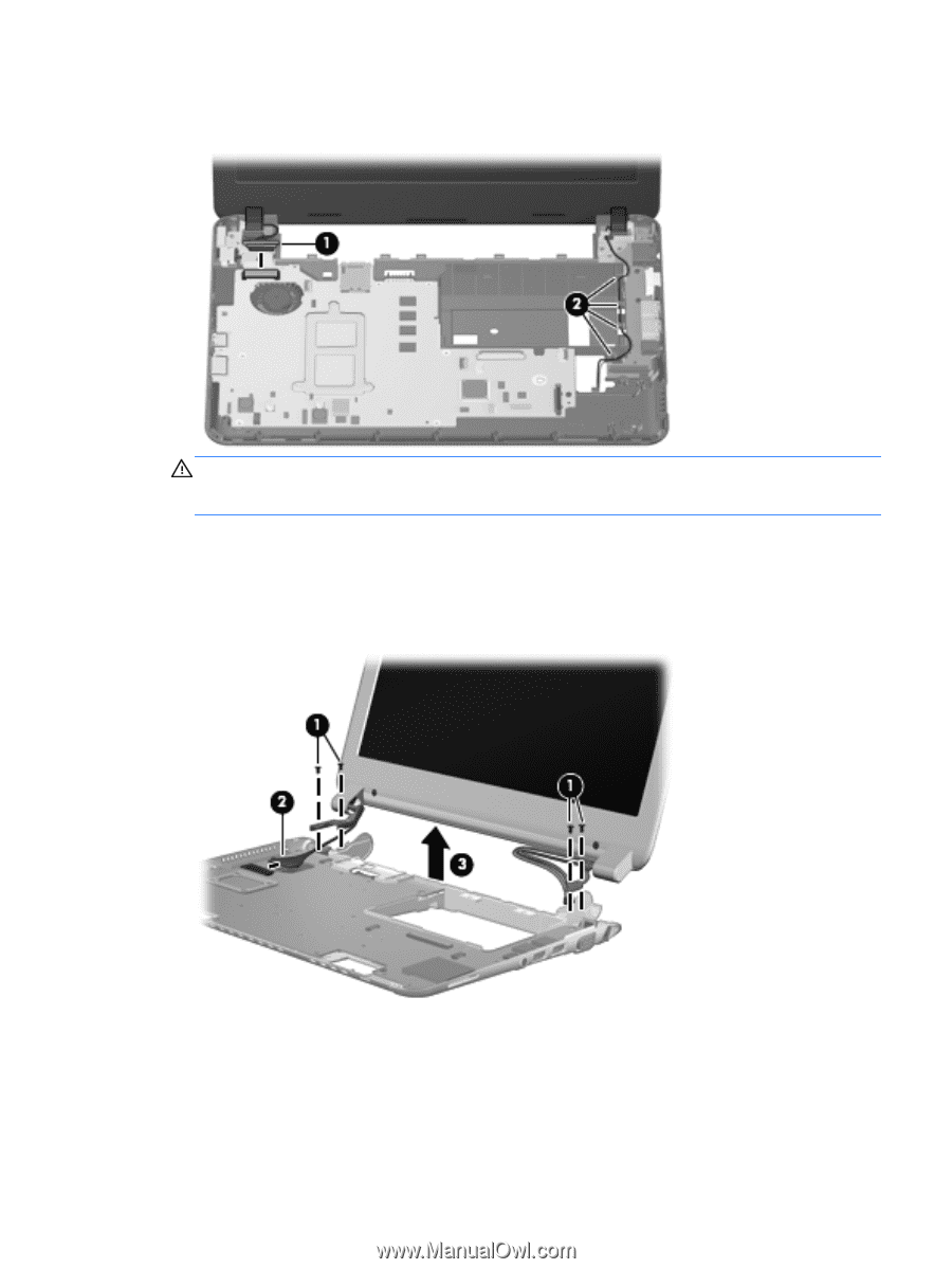
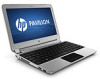
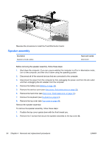
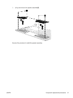
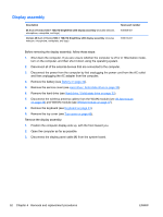
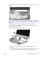
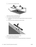
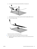
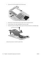
4. Remove the wireless antenna cables from the clips (2) and routing channel built into the base enclosure. CAUTION: Support the display assembly when removing the following screws. Failure to support the display assembly can result in damage to the display assembly and other computer components. 5. Remove the 4 screws (1) that secure the display assembly to the base enclosure. 6. Slide the display panel cable (2) back toward the display assembly while lifting the display assembly (3) straight up to remove it. 7. Lift the display assembly (3) straight up and remove it. 8. If it is necessary to replace the display bezel or any of the display assembly internal components: a. Flex the inside edges of the top edge (1), the left and right sides (2), and the bottom edge (3) of the display bezel until the bezel disengages from the display enclosure. ENWW Component replacement procedures 53
-
 1
1 -
2
-
3
-
4
-
5
-
6
-
7
-
8
-
9
-
10
-
11
-
12
-
13
-
14
-
15
-
16
-
17
-
18
-
19
-
20
-
21
-
22
-
23
-
24
-
25
-
26
-
27
-
28
-
29
-
30
-
31
-
32
-
33
-
34
-
35
-
36
-
37
-
38
-
39
-
40
-
41
-
42
-
43
-
44
-
45
-
46
-
47
-
48
-
49
-
50
-
51
-
52
-
53
-
54
-
55
-
 56
56 -
 57
57 -
 58
58 -
 59
59 -
 60
60 -
 61
61 -
 62
62 -
 63
63 -
 64
64 -
 65
65 -
 66
66 -
67
-
68
-
69
-
70
-
71
-
72
-
73
-
74
-
75
-
76
-
77
-
78
-
79
-
80
-
81
-
82
-
83
-
84
-
85
-
86
-
87
-
88
-
89
-
90
-
91
-
92
-
93
-
94
-
95
-
96
-
97
-
98
-
99
-
100
-
101
-
102
-
103
-
104
-
105
-
106
 |
 |