HP Pavilion dm1-3000 HP Pavilion dm1 Notebook PC - Maintenance and Service Gui - Page 72
RJ-45 connector, System board see
 |
View all HP Pavilion dm1-3000 manuals
Add to My Manuals
Save this manual to your list of manuals |
Page 72 highlights
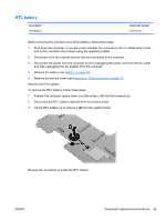
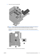
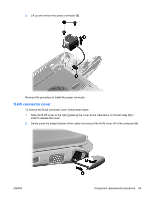
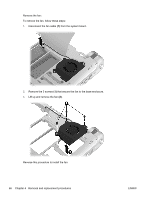
Reverse this procedure to install the RJ-45 connector cover. RJ-45 connector Description RJ-45 connector (includes cable) Spare part number 636452-001 Before removing the RJ-45 connector, follow these steps: 1. Shut down the computer. If you are unsure whether the computer is off or in Hibernation mode, turn on the computer, and then shut it down using the operating system. 2. Disconnect all of the external devices that are connected to the computer. 3. Disconnect the power from the computer by first unplugging the power cord from the AC outlet and then unplugging the AC adapter from the computer. 4. Remove the battery (see Battery on page 32). 5. Remove the following components: a. Service cover (see Hard drive / Solid state drive on page 33). b. Hard drive (see Hard drive / Solid state drive on page 33). c. Keyboard (see Keyboard on page 43). d. Top cover (see Top cover on page 46). e. Display assembly (see Display assembly on page 52). f. System board (see System board on page 57). Remove the RJ-45 connector: To remove the RJ-45 connector, follow these steps: 1. Remove the 2 screws that secure the RJ-45 connector to the base enclosure (1). 2. Lift up and remove the RJ-45 connector (2). 64 Chapter 4 Removal and replacement procedures ENWW
-
 1
1 -
2
-
3
-
4
-
5
-
6
-
7
-
8
-
9
-
10
-
11
-
12
-
13
-
14
-
15
-
16
-
17
-
18
-
19
-
20
-
21
-
22
-
23
-
24
-
25
-
26
-
27
-
28
-
29
-
30
-
31
-
32
-
33
-
34
-
35
-
36
-
37
-
38
-
39
-
40
-
41
-
42
-
43
-
44
-
45
-
46
-
47
-
48
-
49
-
50
-
51
-
52
-
53
-
54
-
55
-
56
-
57
-
58
-
59
-
60
-
61
-
62
-
63
-
64
-
65
-
66
-
 67
67 -
 68
68 -
 69
69 -
 70
70 -
 71
71 -
 72
72 -
 73
73 -
 74
74 -
 75
75 -
 76
76 -
 77
77 -
78
-
79
-
80
-
81
-
82
-
83
-
84
-
85
-
86
-
87
-
88
-
89
-
90
-
91
-
92
-
93
-
94
-
95
-
96
-
97
-
98
-
99
-
100
-
101
-
102
-
103
-
104
-
105
-
106
 |
 |