HP Pavilion dm1-3000 HP Pavilion dm1 Notebook PC - Maintenance and Service Gui - Page 66
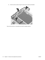
until it rests at an angle., by sliding it away from the base enclosure at a 45-degree angle.
 |
View all HP Pavilion dm1-3000 manuals
Add to My Manuals
Save this manual to your list of manuals |
Page 66 highlights
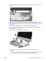
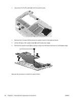
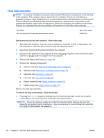
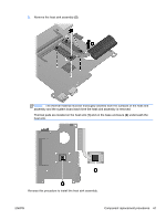
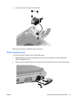
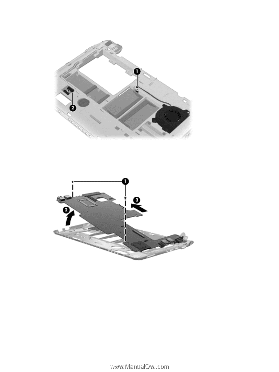
2. Disconnect the RJ-45 cable (2) from the system board. 3. Remove the 2 screws (1) that secure the system board to the base enclosure. 4. Lift the left side of the system board (2) until it rests at an angle. 5. Remove the system board (3) by sliding it away from the base enclosure at a 45-degree angle. Reverse the procedure to install the system board. 58 Chapter 4 Removal and replacement procedures ENWW
-
 1
1 -
2
-
3
-
4
-
5
-
6
-
7
-
8
-
9
-
10
-
11
-
12
-
13
-
14
-
15
-
16
-
17
-
18
-
19
-
20
-
21
-
22
-
23
-
24
-
25
-
26
-
27
-
28
-
29
-
30
-
31
-
32
-
33
-
34
-
35
-
36
-
37
-
38
-
39
-
40
-
41
-
42
-
43
-
44
-
45
-
46
-
47
-
48
-
49
-
50
-
51
-
52
-
53
-
54
-
55
-
56
-
57
-
58
-
59
-
60
-
 61
61 -
 62
62 -
 63
63 -
 64
64 -
 65
65 -
 66
66 -
 67
67 -
 68
68 -
 69
69 -
 70
70 -
 71
71 -
72
-
73
-
74
-
75
-
76
-
77
-
78
-
79
-
80
-
81
-
82
-
83
-
84
-
85
-
86
-
87
-
88
-
89
-
90
-
91
-
92
-
93
-
94
-
95
-
96
-
97
-
98
-
99
-
100
-
101
-
102
-
103
-
104
-
105
-
106
 |
 |
2.
Disconnect the RJ-45 cable
(2)
from the system board.
3.
Remove the 2 screws
(1)
that secure the system board to the base enclosure.
4.
Lift the left side of the system board
(2)
until it rests at an angle.
5.
Remove the system board
(3)
by sliding it away from the base enclosure at a 45-degree angle.
Reverse the procedure to install the system board.
58
Chapter 4
Removal and replacement procedures
ENWW