HP rp5800 Hardware Reference Guide HP rp5800
HP rp5800 Manual
 |
View all HP rp5800 manuals
Add to My Manuals
Save this manual to your list of manuals |
HP rp5800 manual content summary:
- HP rp5800 | Hardware Reference Guide HP rp5800 - Page 1
Hardware Reference Guide HP rp5800 - HP rp5800 | Hardware Reference Guide HP rp5800 - Page 2
. The only warranties for HP products and services are set forth in the express warranty statements accompanying such products and services. Nothing herein should be construed as constituting an additional warranty. HP shall not be liable for technical or editorial errors or omissions contained - HP rp5800 | Hardware Reference Guide HP rp5800 - Page 3
About This Book This guide provides basic information for upgrading this computer model. WARNING! Text set off in this manner indicates that failure to follow directions could result in bodily harm or loss of life. CAUTION: Text set off in this manner indicates that failure to follow directions - HP rp5800 | Hardware Reference Guide HP rp5800 - Page 4
iv About This Book ENWW - HP rp5800 | Hardware Reference Guide HP rp5800 - Page 5
from Desktop to Tower Configuration 4 Installing the Optional Port Cover ...5 Serial Number Location ...6 2 Hardware Upgrades ...7 Warnings and Cautions ...7 Removing the Computer Access Panel 8 Replacing the Computer Access Panel 8 Removing the Front Bezel ...9 Installing an Optical Drive Bezel - HP rp5800 | Hardware Reference Guide HP rp5800 - Page 6
Secondary Hard Drive into a Drive Bay 47 Removing and Replacing the Primary 3.5-inch Internal Hard Drive 48 Appendix A Battery Replacement ...52 Appendix B External Security Devices ...54 Installing a Security Lock ...54 HP/Kensington MicroSaver Security Cable Lock 54 Padlock ...55 HP Business PC - HP rp5800 | Hardware Reference Guide HP rp5800 - Page 7
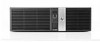
with an optical drive and optical drive bezel. Figure 1-1 HP Point of Sale System rp5800 Configuration NOTE: This product features optional Powered USB ports. In the point of sale industry, "Powered USB" is also referred to as "USB + Power," "USB Plus Power," and "Retail USB." In this document - HP rp5800 | Hardware Reference Guide HP rp5800 - Page 8
link light indicates a network connection. The NIC activity light indicates network activity. The Power On Light is normally green when the power is on. If it is flashing red, there is a problem with the computer and it is displaying a diagnostic code. Refer to the Maintenance and Service Guide to - HP rp5800 | Hardware Reference Guide HP rp5800 - Page 9
adapter and an optional parallel port are available from HP. The serial ports can be configured as 5V or 12V powered serial ports. CAUTION: The cash drawer connector is similar in size and shape to a modem jack. To avoid damage to the computer, DO NOT plug a network cable into the cash drawer - HP rp5800 | Hardware Reference Guide HP rp5800 - Page 10
from Desktop to Tower Configuration The computer can be used in a tower orientation with an optional tower stand that can be purchased from HP. 1. Remove all removable media, such as compact discs or USB flash drives, from the computer. 2. Turn off the computer properly through the operating system - HP rp5800 | Hardware Reference Guide HP rp5800 - Page 11
Cover The computer can support an optional rear port cover that can be installed to hide the rear ports and cables. The doors on top of the port cover can be opened and snapped back to allow room for a security lock if one is attached to the rear of the computer. To install the port cover: 1. If - HP rp5800 | Hardware Reference Guide HP rp5800 - Page 12
two captive screws on the bottom of the port cover to secure it in place. Figure 1-6 Securing the Port Cover 4. The port cover is designed to allow cables to route out of the back of the computer horizontally or vertically. Figure 1-7 Cable Routing Serial Number Location Each computer has a unique - HP rp5800 | Hardware Reference Guide HP rp5800 - Page 13
describes proper workstation, setup, posture, and health and work habits for computer users, and provides important electrical and mechanical safety information. This guide is located on the Web at http://www.hp.com/ergo. WARNING! Energized and moving parts inside. Disconnect power to the equipment - HP rp5800 | Hardware Reference Guide HP rp5800 - Page 14
Remove all removable media, such as compact discs or USB flash drives, from the computer. 3. Turn off the computer properly through the operating system, then turn off any external devices. 4. Disconnect the power cord from the power outlet and disconnect any external devices. CAUTION: Regardless of - HP rp5800 | Hardware Reference Guide HP rp5800 - Page 15
Remove all removable media, such as compact discs or USB flash drives, from the computer. 3. Turn off the computer properly through the operating system, then turn off any external devices. 4. Disconnect the power cord from the power outlet and disconnect any external devices. CAUTION: Regardless of - HP rp5800 | Hardware Reference Guide HP rp5800 - Page 16
an Optical Drive Bezel On some models there is a driveless bezel in place of the optical drive bezel that must be replaced with an optical drive bezel if you are installing an optical drive. To install an optical drive bezel: 1. Remove the access panel and front bezel. 2. Press each of the - HP rp5800 | Hardware Reference Guide HP rp5800 - Page 17
Removing a Bezel Blank On some models, there is a bezel blank covering the optical drive bay that must be removed before installing a drive. To remove a bezel blank: 1. Remove the access panel and front bezel. 2. Push outward on the two retaining tabs that hold the bezel blank in place (1) - HP rp5800 | Hardware Reference Guide HP rp5800 - Page 18
can be populated with up to four industry-standard DIMMs. These memory sockets are populated with at least one preinstalled DIMM. To achieve the maximum memory support, you can populate the system board with up to 16-GB of memory configured in a high-performing dual channel mode. DDR3-SDRAM DIMMs - HP rp5800 | Hardware Reference Guide HP rp5800 - Page 19
mode, or flex mode, depending on how the DIMMs are installed. ● The system will operate in single channel mode if the DIMM sockets are populated in one channel only. ● The system will operate in a higher-performing dual channel mode if the total memory capacity of the DIMMs in Channel A is equal to - HP rp5800 | Hardware Reference Guide HP rp5800 - Page 20
DIMM in the system. Installing DIMMs CAUTION: You must disconnect the power cord and wait approximately 30 seconds for the power to drain before adding or removing memory modules. Regardless of the power-on state, voltage is always supplied to the memory modules as long as the computer is plugged - HP rp5800 | Hardware Reference Guide HP rp5800 - Page 21
bay housing to access the memory module sockets on the system board. Figure 2-9 Rotating the Drive Cage Up 8. Open both latches of the memory module socket (1), and insert the memory module into the socket (2). Figure 2-10 Installing a DIMM NOTE: A memory module can be installed in only one way - HP rp5800 | Hardware Reference Guide HP rp5800 - Page 22
(3). 10. Repeat steps 8 and 9 to install any additional modules. 11. Rotate the drive cage back down to its normal position. CAUTION: drive cage down. Figure 2-11 Rotating the Drive Cage Down 12. Replace the access panel. 13. If the computer was on a stand, replace the stand. 14. Reconnect the power - HP rp5800 | Hardware Reference Guide HP rp5800 - Page 23
plug any other type of card into this slot. NOTE: The following sections provide instructions for installing a Powered USB expansion card. However, the procedure is basically the same for installing any PCI Express expansion card into a PCI Express x1 expansion slot or PC Express x16 expansion slot - HP rp5800 | Hardware Reference Guide HP rp5800 - Page 24
socket on the system board and the corresponding expansion slot on the back of the computer chassis. NOTE: You can install the Powered USB expansion card in either the PCI Express x1 slot or the PCI Express x16 slot, or both. Two 12-volt Powered USB expansion cards are supported. 18 Chapter - HP rp5800 | Hardware Reference Guide HP rp5800 - Page 25
Release the half-height slot cover retention latch by lifting the green tab on the latch and rotating the latch to the open position. Figure 2-14 Opening the Half-Height Slot Cover Retention Latch 9. Before installing an expansion card, remove the expansion slot cover or the existing expansion card - HP rp5800 | Hardware Reference Guide HP rp5800 - Page 26
to the expansion card. a. If you are installing an expansion card in a vacant card, hold the card at each end, and carefully rock it back and forth until the connectors pull free from the socket. Pull the expansion card straight up from the socket then away from the inside of the chassis to release - HP rp5800 | Hardware Reference Guide HP rp5800 - Page 27
and forth until the connectors pull free from the socket. Pull the expansion card straight up from the socket then away from the inside of the chassis to release it from the chassis frame. Be sure not to scrape the card against the other components. Figure 2-16 Removing a PCI Express x16 Expansion - HP rp5800 | Hardware Reference Guide HP rp5800 - Page 28
on the system board (2). NOTE: You can install the Powered USB expansion card in either the PCI Express x1 slot or the PCI Express x16 slot, or both. Two 12-volt Powered USB expansion cards are supported. Figure 2-17 Installing a 12-volt Powered USB Expansion Card NOTE: When installing an expansion - HP rp5800 | Hardware Reference Guide HP rp5800 - Page 29
Connect the black connector to one of the two black 12-volt USB connectors on the system board (3). NOTE: The system board connectors allow you to install two 12-volt Powered USB expansion cards. The green connectors on the system board are coupled together as one connector. The black connectors on - HP rp5800 | Hardware Reference Guide HP rp5800 - Page 30
bottom slot on each card (3) is designed specifically for an HP Powered Serial Port expansion card. DO NOT attempt to plug any other type of card into the bottom slot. NOTE: The following sections provide instructions for installing a Powered Serial Port expansion card. However, the procedure is - HP rp5800 | Hardware Reference Guide HP rp5800 - Page 31
port expansion card installed that supplies two additional powered serial ports, COM 3 and COM 4. If your computer is not configured with a powered serial port expansion card, you may purchase one from HP. Figure 2-21 Powered Serial Ports Table 2-5 Powered Serial Ports Item Description Supports - HP rp5800 | Hardware Reference Guide HP rp5800 - Page 32
Caps To install a Powered Serial Port expansion card: 1. Remove/disengage any security devices that prohibit opening the computer. 2. Remove all removable media, such as compact discs or USB flash drives, from the computer. 3. Turn off the computer properly through the operating system, then turn - HP rp5800 | Hardware Reference Guide HP rp5800 - Page 33
make sure they are unplugged from the rear of the computer so that the connectors do not block the power supply from rotating all the way back. Figure 2-23 Raising the Power Supply 8. Pull back the green tab on the full-height expansion card retention latch to open the latch. Figure 2-24 Opening the - HP rp5800 | Hardware Reference Guide HP rp5800 - Page 34
Powered Serial Port expansion card must be installed in the bottom socket on the riser card. The bottom socket is designed specifically for that card. DO NOT attempt to install any other card in the bottom socket. Figure 2-26 Installing the Powered Serial Port Expansion Card in the Riser Card 28 - HP rp5800 | Hardware Reference Guide HP rp5800 - Page 35
11. Close the expansion card retention latch. Figure 2-27 Closing the Expansion Card Retention Latch 12. Rotate the power supply back down to its normal position. Figure 2-28 Lowering the Power Supply 13. Replace the computer access panel. 14. If the computer was on a stand, replace the stand. 15. - HP rp5800 | Hardware Reference Guide HP rp5800 - Page 36
require an external power source. NOTE: The computer ships with all serial ports configured in standard serial mode by default unless the powered serial port AV numbers are ordered. The serial ports on the HP Point of Sale System computer can be configured using the Computer F10 Setup utility. Under - HP rp5800 | Hardware Reference Guide HP rp5800 - Page 37
card: 1. Remove/disengage any security devices that prohibit opening the computer. 2. Remove all removable media, such as compact discs or USB flash drives, from the computer. 3. Turn off the computer properly through the operating system, then turn off any external devices. 4. Disconnect the power - HP rp5800 | Hardware Reference Guide HP rp5800 - Page 38
the green tab on the full-height expansion card retention latch to open the latch. Figure 2-30 Opening the Full-Height Slot Cover Retention Latch 9. If a one or two expansion cards are installed in any of the riser card expansion slots, remove the cards. Figure 2-31 Removing a Full-Height Expansion - HP rp5800 | Hardware Reference Guide HP rp5800 - Page 39
10. To remove the riser card, disconnect the hood sensor cable from the system board (1), pull back the arm on the back of the riser card slot (2), then lift the riser card out of the riser card slot (3). Figure 2-32 Removing the Riser Card 11. Remove the two screws that secure the metal bracket to - HP rp5800 | Hardware Reference Guide HP rp5800 - Page 40
the metal bracket onto the new riser card using the two screws that secure the bracket in place. Figure 2-34 Installing the Riser Card Bracket 13. To install the new riser card, press the riser card firmly down into the riser card slot on the system board (1) and plug the hood sensor cable into - HP rp5800 | Hardware Reference Guide HP rp5800 - Page 41
were removed from the old riser card, install the cards into the appropriate slots on the new riser card. Move the card toward the rear of the chassis so that the bracket on the card is aligned with the open slot on the rear of the chassis (1). Press the card straight down into the expansion socket - HP rp5800 | Hardware Reference Guide HP rp5800 - Page 42
down to its normal position. Figure 2-38 Lowering the Power Supply 17. Replace the computer access panel. 18. If the computer was on a stand, replace the stand. 19. Reconnect the power cord and any external devices, then turn on the computer. 20. Lock any security devices that were disengaged when - HP rp5800 | Hardware Reference Guide HP rp5800 - Page 43
computer, run Computer Setup. Installing and Removing Drives When installing drives, follow these guidelines: ● The computer supports up to three drives in the following configurations: ◦ Two hard drives and one optical drive ◦ Two hard drives and one eSATA drive ◦ One hard drive, one optical drive - HP rp5800 | Hardware Reference Guide HP rp5800 - Page 44
HP-supplied metric screws are black and the HP-supplied standard screws are silver. If you are replacing the primary hard drive, you must remove the four silver and blue 6-32 isolation mounting guide screws from the old hard drive and install them in the new hard drive. Figure 2-40 Extra Guide Screw - HP rp5800 | Hardware Reference Guide HP rp5800 - Page 45
No. System Board Connector System Board Label 1 SATA0 SATA0 2 SATA1 SATA1 3 eSATA SATA2 Color dark blue light blue black Device Primary Hard Drive Secondary Hard Drive or Optical Drive if an eSATA Adapter is present eSATA Adapter or Optical Drive ENWW Installing and Removing Drives 39 - HP rp5800 | Hardware Reference Guide HP rp5800 - Page 46
Remove all removable media, such as compact discs or USB flash drives, from the computer. 3. Turn off the computer properly through the operating system, then turn off any external devices. 4. Disconnect the power cord from the power outlet and disconnect any external devices. CAUTION: Regardless of - HP rp5800 | Hardware Reference Guide HP rp5800 - Page 47
CAUTION: When removing the cables, pull the tab or connector instead of the cable itself to avoid damaging the cable. Figure 2-43 Disconnecting the Power and Data Cables 9. Rotate the drive cage back down to its normal position. CAUTION: Be careful not to pinch any cables or wires when rotating the - HP rp5800 | Hardware Reference Guide HP rp5800 - Page 48
Remove all removable media, such as compact discs or USB flash drives, from the computer. 3. Turn off the computer properly through the operating system, then turn off any external devices. 4. Disconnect the power cord from the power outlet and disconnect any external devices. CAUTION: Regardless of - HP rp5800 | Hardware Reference Guide HP rp5800 - Page 49
5-mm long screws as guide screws. Longer screws can damage the internal components of the drive. Figure 2-46 Installing Guide Screws in the Optical Drive 9. Position the guide screws on the drive into the J-slots in the drive bay. Then slide the drive toward the front of the computer until it locks - HP rp5800 | Hardware Reference Guide HP rp5800 - Page 50
board to the primary hard drive, then to the secondary hard drive, then to the rear of the optical drive. Figure 2-49 Connecting the Power and Data Cables 12. Connect the SATA data cable to the black eSATA connector on the system board labeled SATA2 unless an eSATA adapter is installed. If an eSATA - HP rp5800 | Hardware Reference Guide HP rp5800 - Page 51
a 5.25-inch Optical Drive from a Drive Bay on page 40 to remove the optical drive and access the secondary hard drive. CAUTION: Ensure that the computer is turned off and that the power cord is disconnected from the electrical outlet before proceeding. ENWW Installing and Removing Drives 45 - HP rp5800 | Hardware Reference Guide HP rp5800 - Page 52
back of the hard drive. Figure 2-51 Disconnecting the Secondary Hard Drive Power and Data Cables 3. Press down on the green drive retainer button located on the left side of the drive to disengage the drive from the drive cage (1). While pressing the drive retainer button, slide the drive back until - HP rp5800 | Hardware Reference Guide HP rp5800 - Page 53
and access the 3.5-inch secondary hard drive bay. CAUTION: Ensure that the computer is turned off and that the power cord is disconnected from the electrical outlet before proceeding. 2. Install four 6-32 standard guide screws in the holes on each side of the drive. HP has provided four extra 6-32 - HP rp5800 | Hardware Reference Guide HP rp5800 - Page 54
the power supply. To remove and replace the primary hard drive: 1. Remove/disengage any security devices that prohibit opening the computer. 2. Remove all removable media, such as compact discs or USB flash drives, from the computer. 3. Turn off the computer properly through the operating system - HP rp5800 | Hardware Reference Guide HP rp5800 - Page 55
from the stand. 6. Remove the computer access panel. 7. Rotate the drive cage for internal drives to its upright position. Figure 2-56 Rotating the Drive Cage Up 8. Rotate the power supply to its upright position. The hard drive is located beneath the power supply. NOTE: If you are using a PS - HP rp5800 | Hardware Reference Guide HP rp5800 - Page 56
and out of the bay (2). Figure 2-59 Removing the Hard Drive 11. To install a hard drive, you must transfer the silver and blue isolation mounting guide screws from the old hard drive to the new hard drive. Figure 2-60 Installing Primary Hard Drive Guide Screws 50 Chapter 2 Hardware Upgrades ENWW - HP rp5800 | Hardware Reference Guide HP rp5800 - Page 57
Hard Drive Power and Data Cables NOTE: Refer to System Board Drive Connections on page 39 for an illustration of the system board drive connectors. 14. Rotate the drive cage for internal drives and the power supply down to their normal positions. 15. Replace the access panel. 16. If the computer - HP rp5800 | Hardware Reference Guide HP rp5800 - Page 58
Remove all removable media, such as compact discs or USB flash drives, from the computer. 3. Turn off the computer properly through the operating system, then turn off any external devices. 4. Disconnect the power cord from the power outlet and disconnect any external devices. CAUTION: Regardless of - HP rp5800 | Hardware Reference Guide HP rp5800 - Page 59
7. To release the battery from its holder, squeeze the metal clamp that extends above one the computer access panel. 10. Reconnect the power cord and any external devices, then turn on the computer. 11. Reset the date and time, your passwords, and any special system setups using Computer Setup. 12 - HP rp5800 | Hardware Reference Guide HP rp5800 - Page 60
B External Security Devices Installing a Security Lock The security locks displayed below and on the following pages can be used to secure the computer. HP/Kensington MicroSaver Security Cable Lock Figure B-1 Installing a Cable Lock 54 Appendix B External Security Devices ENWW - HP rp5800 | Hardware Reference Guide HP rp5800 - Page 61
Padlock Figure B-2 Installing a Padlock ENWW Installing a Security Lock 55 - HP rp5800 | Hardware Reference Guide HP rp5800 - Page 62
HP Business PC Security Lock 1. Fasten the security cable by looping it around a stationary object. Figure B-3 Securing the Cable to a Fixed Object 2. Insert the Kensington lock into the Kensington lock slot on the back of the monitor and secure the lock to the monitor by inserting the key into the - HP rp5800 | Hardware Reference Guide HP rp5800 - Page 63
two holes in the bracket (2). Use the hole in the bracket that best secures the peripheral device cable. Figure B-6 Securing Peripheral Devices (Printer Shown) ENWW Installing a Security Lock 57 - HP rp5800 | Hardware Reference Guide HP rp5800 - Page 64
5. Thread the keyboard and mouse cables through the computer chassis lock. Figure B-7 Threading the Keyboard and Mouse Cables 6. Screw the lock to the chassis in the thumbscrew hole using the screw provided. Figure B-8 Attaching the Lock to the Chassis 58 Appendix B External Security Devices ENWW - HP rp5800 | Hardware Reference Guide HP rp5800 - Page 65
the plug end of the security cable into the lock (1) and push the button in (2) to engage the lock. Use the key provided to disengage the lock. Figure B-9 Engaging the Lock 8. When complete, all devices in your workstation will be secured. Figure B-10 Secured Workstation ENWW Installing a Security - HP rp5800 | Hardware Reference Guide HP rp5800 - Page 66
security screw provided by HP. To install the security screw: 1. Remove/disengage any security devices that prohibit opening the computer. 2. Remove all removable media, such as compact discs or USB flash drives, from the computer. 3. Turn off the computer properly through the operating system, then - HP rp5800 | Hardware Reference Guide HP rp5800 - Page 67
middle front bezel release tab to secure the front bezel in place. Figure B-12 Installing the Front Bezel Security Screw 10. Replace the access panel. 11. If the computer was on a stand, replace the stand. 12. Reconnect the power cord and any external devices, then turn on the computer. 13. Lock any - HP rp5800 | Hardware Reference Guide HP rp5800 - Page 68
C-1 Optional Integration Tray and Accessories The following HP Point of Sale System rp5800 integration system options are available from HP: ● Terminal Enclosure Assembly (1) ● Integration Tray Assembly (2) ● Display Pole Mount Assembly (3) ● Optional Display Arm Assembly (not shown) 62 Appendix - HP rp5800 | Hardware Reference Guide HP rp5800 - Page 69
HP Point of Sale System rp5800 peripheral options are available from HP: ● HP Cash Drawer ● HP POS Keyboard ● HP POS MSR Keyboard ● HP Mini MSR ● HP Single Station PUSB Receipt Printer ● POS Dual Serial/USB Receipt Printer ● Hybrid MICR Receipt Printer ● Hybrid MICR/Imager Receipt Printer ● USB - HP rp5800 | Hardware Reference Guide HP rp5800 - Page 70
conductor may damage system boards or other static-sensitive devices. This type of damage may reduce the life expectancy of the when handling or installing electrostatic-sensitive parts: ● Use a wrist strap connected by a ground cord to a grounded workstation or computer chassis. Wrist straps - HP rp5800 | Hardware Reference Guide HP rp5800 - Page 71
and keyboard. ● Never cover the ventilation slots on the monitor with any type of material. ● Install or enable power management functions of the operating system or other software, including sleep states. ● Turn off the computer before you do either of the following: ◦ Wipe the exterior of the - HP rp5800 | Hardware Reference Guide HP rp5800 - Page 72
to ship the computer: 1. Back up the hard drive files on PD discs, tape cartridges, CDs, or USB flash drives. Be sure that the backup media is not exposed to electrical or magnetic impulses while stored or in transit. NOTE: The hard drive locks automatically when the system power is turned off - HP rp5800 | Hardware Reference Guide HP rp5800 - Page 73
locations 24 system board slot locations 17 front panel components 2 G guide screws location 38 H hard drive cable connections 37, 39 primary installation 48 primary removal 48 secondary installation 47 secondary removal 45 I installation guidelines 7 installing 12V Powered USB expansion card 18 - HP rp5800 | Hardware Reference Guide HP rp5800 - Page 74
hard drive installation 47 removal 45 security cable lock 54 front bezel 60 HP Business PC Security Lock 56 padlock 55 serial number location 6 serial ports configuring for power 30 installing expansion card 25 locations 3, 25 removing caps 26 shipping preparation 66 specifications memory 12 T tower
-
 1
1 -
 2
2 -
 3
3 -
 4
4 -
 5
5 -
 6
6 -
 7
7 -
8
-
9
-
10
-
11
-
12
-
13
-
14
-
15
-
16
-
17
-
18
-
19
-
20
-
21
-
22
-
23
-
24
-
25
-
26
-
27
-
28
-
29
-
30
-
31
-
32
-
33
-
34
-
35
-
36
-
37
-
38
-
39
-
40
-
41
-
42
-
43
-
44
-
45
-
46
-
47
-
48
-
49
-
50
-
51
-
52
-
53
-
54
-
55
-
56
-
57
-
58
-
59
-
60
-
61
-
62
-
63
-
64
-
65
-
66
-
67
-
68
-
69
-
70
-
71
-
72
-
73
-
74
 |
 |

Hardware Reference Guide
HP rp5800