Hitachi 42PD8800 Owners Guide - Page 14
CONNECTION, Terminal Positions, Connecting Procedure
 |
View all Hitachi 42PD8800 manuals
Add to My Manuals
Save this manual to your list of manuals |
Page 14 highlights
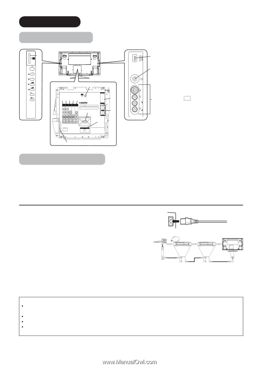
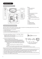
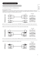
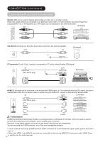
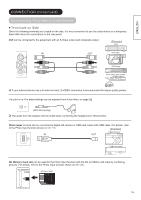
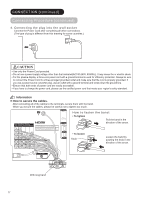
CONNECTION Terminal Positions SD MEMORY CARD h PUSH-EJECT P P OK PH35814 w ANT e rt yu INPUT(RGB) AUDIO PC ANALOG RGB INPUT (AV1) INPUT (AV2) INPUT (AV3) INPUT (AV4) OUTPUT Y/VIDEO Y/VIDEO S-VIDEO PB PB SUB WOOFER WOW, SRS and symbol are trademarks of SRS Labs, Inc. Licensed by BBE Sound, Inc. under USP5510752 and 5736897. BBE and BBE symbol are registered trademarks of BBE Sound, Inc. i PR PR VIDEO VIDEO VIDEO AUDIO AUDIO AUDIO AUDIO AUDIO SERVICE USE ONLY INPUT(HDMI) AUDIO HDMI2 HDMI1 L MONO L MONO L MONO L MONO L C C C C R R R R R o A C POWER SWIVEL a s q Connecting Procedure INPUT(AV5) PH35826 R L/MONO AUDIO VIDEO S-VIDEO Rear q Power Cord Socket g w Aerial Socket e AV1 f r AV2 t AV3 y AV4 u Monitor Out and Sub Woofer i Service use only o Power Swivel Terminal d (see 36 ) a PC Connection terminals (D-sub 15 pin and mini stereo for Audio) s HDMI1, 2 and mini stereo for Audio Side d AV5 f Headphone input g Photo Input terminal h SD Memory Card slot This unit is ready for various kinds of connections. Make a connection in the following steps. Be sure to turn off the Main Power first when connecting external equipments. 1. Connect Power Cord to the rear panel. 2. Connect Aerial Lead. 3. Connect your external equipments to the unit if any. 4. Connect the Power Plug to the Wall Socket. 1. Connecting Power Cord to the Rear Panel Connect Power Cord to the monitor. *Make sure not to connect the Power Plug to the Wall Socket until all connections are completed. 2. Connecting Aerial Lead. There are two ways to connect Aerial Lead. STB VCR q When you do not have any other external equipment: Connect the Aerial Lead directly into the Socket at rear panel. w When you have one or more external devices to connect: 1. Use RF cable to connect between each equipment and Antenna. 2. Connect the Aerial Lead to an equipment'In'Socket IN IN OUT OUT [Example: Connecting Antenna through STB and VCR] marked 3. Connect the RF cable from the equipment 'Out' to the other equipment 'In.' 4. Then, connect from the equipment 'Out' to "ANT" on the plasma screen Socket on marked . Precautions when connecting the aerial Please use a coaxial cable which is free from interference to connect the aerial. Avoid using a parallel flat feeder wire as interference may occur, causing reception to be unstable and stripe noise to appear on the screen. Avoid using indoor aerial as this may be affected by interference. Please use CATV net or outdoor aerial. For safety, install an external aerial conforming to AS1417.1 (applicable for Australia only) If there are noise appearance in the picture of VHF-Low band channel, please use the double-shielded cable (not provided) for RF LEADS to reduce the noise. 13
-
 1
1 -
2
-
3
-
4
-
5
-
6
-
7
-
8
-
 9
9 -
 10
10 -
 11
11 -
 12
12 -
 13
13 -
 14
14 -
 15
15 -
 16
16 -
 17
17 -
 18
18 -
 19
19 -
20
-
21
-
22
-
23
-
24
-
25
-
26
-
27
-
28
-
29
-
30
-
31
-
32
-
33
-
34
-
35
-
36
-
37
-
38
-
39
-
40
-
41
-
42
-
43
-
44
-
45
-
46
-
47
-
48
-
49
-
50
-
51
-
52
-
53
-
54
-
55
-
56
-
57
-
58
-
59
-
60
-
61
-
62
 |
 |