IBM 43635gu User Guide - Page 44
Installing a tape drive, Read the safety information that begins on v and Installation guidelines
 |
UPC - 883436002950
View all IBM 43635gu manuals
Add to My Manuals
Save this manual to your list of manuals |
Page 44 highlights
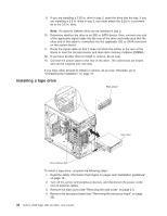
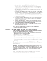
9. If you are installing a 5.25 in. drive in bay 2, push the drive into the bay. If you are installing a 3.5 in. drive in bay 2, you must attach the 5.25 in. conversion kit to the 3.5 in. drive. Note: An optional diskette drive can be installed in bay 3. 10. Determine whether the drive is an IDE or SATA device; then, connect one end of the applicable signal cable into the rear of the drive and make sure that the other end of this cable is connected into the applicable IDE or SATA connector on the system board. 11. Route the signal cable so that it does not block the airflow to the rear of the drives or over the microprocessor and dual inline memory modules (DIMMs). 12. If you have another drive to install or remove, do so now. 13. Connect the power cable to the rear of the drive. The connectors are keyed and can be inserted only one way. If you have other devices to install or remove, do so now; otherwise, go to "Completing the installation" on page 47. Installing a tape drive EMC shield Tape drive Drive retainer clip To install a tape drive, complete the following steps: 1. Read the safety information that begins on pagev and "Installation guidelines" on page 18. 2. Turn off the server and peripheral devices, and disconnect the power cords and all external cables. 3. Remove the side cover (see "Removing the side cover" on page 21). 4. Remove the two-piece bezel (see "Removing the two-piece bezel" on page 22). 30 System x3200 Types 4362 and 4363: User's Guide
-
 1
1 -
2
-
3
-
4
-
5
-
6
-
7
-
8
-
9
-
10
-
11
-
12
-
13
-
14
-
15
-
16
-
17
-
18
-
19
-
20
-
21
-
22
-
23
-
24
-
25
-
26
-
27
-
28
-
29
-
30
-
31
-
32
-
33
-
34
-
35
-
36
-
37
-
38
-
 39
39 -
 40
40 -
 41
41 -
 42
42 -
 43
43 -
 44
44 -
 45
45 -
 46
46 -
 47
47 -
 48
48 -
 49
49 -
50
-
51
-
52
-
53
-
54
-
55
-
56
-
57
-
58
-
59
-
60
-
61
-
62
-
63
-
64
-
65
-
66
-
67
-
68
-
69
-
70
-
71
-
72
-
73
-
74
-
75
-
76
-
77
-
78
-
79
-
80
-
81
-
82
-
83
-
84
-
85
-
86
-
87
-
88
 |
 |
