IBM 43635gu User Guide - Page 49
Power and signal cables for internal drives, Power cables, Signal cables, Optional Diskette drive
 |
UPC - 883436002950
View all IBM 43635gu manuals
Add to My Manuals
Save this manual to your list of manuals |
Page 49 highlights
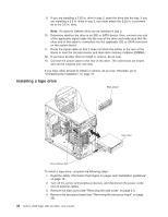
Power and signal cables for internal drives The server uses cables to connect parallel IDE, simple-swap SATA, and SAS devices to the power supply and to the system board. (See "System-board internal connectors" on page 14 for the location of system-board connectors.) Review the following information before you connect power and signal cables to internal drives: v The drives that are preinstalled in the server come with power and signal cables attached. If you replace any drives, remember which cable is attached to which drive. v When you install a drive, make sure that one of the signal cable drive connectors is connected to the drive and that the connector at the other end of the signal cable is connected to the system board or a compatible adapter or controller that you have installed. v If you have only one IDE device on a cable, it must be set as a master device. v If two IDE devices are used on a single cable, one must be designated as the master device and the other as the subordinate device; otherwise, the server might not recognize some of the IDE devices. The master and subordinate designation is determined by switch or jumper settings on each IDE device. v When you route a cable, make sure that it does not block the airflow to the rear of the drives or over the microprocessor or DIMMs. The following cables are provided: v Power cables: Four-wire power cables connect the drives to the power supply. At the end of these cables are plastic connectors that can be attached to different drives; these connectors vary in size. Use either a four-wire power cable or SATA power cable with SATA drives, but do not use both at the same time (use one or the other). v Signal cables: Signal cables are typically flat cables, also called ribbon cables, that connect parallel IDE, SATA, SAS, and diskette drives to the system board. Two or three types of signal cables come with the server: - IDE: The wider IDE signal cable has three connectors. One of these connectors is attached to the drive, one is a spare, and the third is attached to the primary or secondary IDE connector on the system board. The spare connector can be used to connect an additional IDE drive to the server. The CD drive is attached to an ATA 100 signal cable. ATA 100 signal cables are color-coded. The blue connector is attached to the system board. The black connector is attached to the master IDE device. The gray middle connector is attached to the subordinate IDE device. - (Optional) Diskette drive: The narrower signal cable has two connectors. One is attached to the diskette drive, and the other is attached to the connector (FDD1) on the system board. - Simple-swap SATA: Simple-swap SATA models come with four SATA cables that are already connected to the system board and the back panel at the rear of the simple-swap drives. - Hot-swap SATA: Hot-swap SATA models come with a single data cable that connects the SAS/SATA controller to the hot-swap backplane. This cable provides inherent connectivity for the four SATA drives that the server supports. Therefore, additional cabling is not required for these drives. - SAS: Hot-swap SAS models come with a single data cable that connects the SAS/SATA controller to the hot-swap backplane. This cable provides inherent connectivity for the four SAS drives that the server supports. Therefore, additional cabling is not required for these drives. Chapter 2. Installing optional devices 35
-
 1
1 -
2
-
3
-
4
-
5
-
6
-
7
-
8
-
9
-
10
-
11
-
12
-
13
-
14
-
15
-
16
-
17
-
18
-
19
-
20
-
21
-
22
-
23
-
24
-
25
-
26
-
27
-
28
-
29
-
30
-
31
-
32
-
33
-
34
-
35
-
36
-
37
-
38
-
39
-
40
-
41
-
42
-
43
-
 44
44 -
 45
45 -
 46
46 -
 47
47 -
 48
48 -
 49
49 -
 50
50 -
 51
51 -
 52
52 -
 53
53 -
 54
54 -
55
-
56
-
57
-
58
-
59
-
60
-
61
-
62
-
63
-
64
-
65
-
66
-
67
-
68
-
69
-
70
-
71
-
72
-
73
-
74
-
75
-
76
-
77
-
78
-
79
-
80
-
81
-
82
-
83
-
84
-
85
-
86
-
87
-
88
 |
 |
