IBM 8676 Installation Guide - Page 29
Installing a microprocessor, Advanced Setup, Memory Settings, Enable, Boot Fail, Count, Start Options
 |
UPC - 087944770107
View all IBM 8676 manuals
Add to My Manuals
Save this manual to your list of manuals |
Page 29 highlights
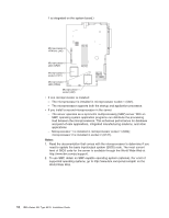
5. Install the DIMM in the slot: a. Open the retention latches and insert the DIMM straight into the slot, pressing down on both corners of the DIMM at the same time. The side of the DIMM with the gold-edge connectors has an index slot, offset from the center of the DIMM. Align the index slot with the slot on the system board. Ensure that no gap exists between the DIMM and the retaining clips. If a gap does exist, remove the DIMM; then, reinsert it correctly b. If you replaced a failed DIMM, start the Configuration/Setup Utility program, select Advanced Setup, select Memory Settings, highlight the connector or bank of connectors that you want to enable, and then select Enable. With some memory configurations, the 3-3-3 beep code might sound during POST, followed by a blank display screen. If this occurs and the Boot Fail Count feature in the Start Options of the Configuration/Setup Utility program is enabled (its default setting), restart the server three times to force the BIOS to reset the memory connector or bank of connectors. 6. If you have other options to install, install them now. Otherwise, go to "Completing the installation" on page 21. Installing a microprocessor This section describes how to install a microprocessor in the server. Before you install a microprocessor, review the following information: v The server comes with one microprocessor installed. The following illustration shows the microprocessor sockets and the pluggable microprocessor 2 voltage regulator module (VRM) slot on the system board. (The VRM for microprocessor Chapter 2. Installing options 17
-
 1
1 -
2
-
3
-
4
-
5
-
6
-
7
-
8
-
9
-
10
-
11
-
12
-
13
-
14
-
15
-
16
-
17
-
18
-
19
-
20
-
21
-
22
-
23
-
 24
24 -
 25
25 -
 26
26 -
 27
27 -
 28
28 -
 29
29 -
 30
30 -
 31
31 -
 32
32 -
 33
33 -
 34
34 -
35
-
36
-
37
-
38
-
39
-
40
-
41
-
42
-
43
-
44
-
45
-
46
-
47
-
48
-
49
-
50
-
51
-
52
-
53
-
54
-
55
-
56
-
57
-
58
-
59
-
60
-
61
-
62
-
63
-
64
-
65
-
66
-
67
-
68
-
69
-
70
-
71
-
72
-
73
-
74
-
75
-
76
-
77
-
78
-
79
-
80
-
81
-
82
-
83
-
84
-
85
-
86
-
87
-
88
-
89
-
90
-
91
-
92
 |
 |
