IBM 8676 Installation Guide - Page 34
Cabling the server, Rack Installation Instruction, User's Guide
 |
UPC - 087944770107
View all IBM 8676 manuals
Add to My Manuals
Save this manual to your list of manuals |
Page 34 highlights
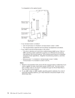
engages the tabs at the front and rear of the server. 3. If you removed the bezel, position the bezel directly in front of the server and press it into place so that the retention tabs snap into the holes on the top, right side, and bottom of the server. 4. If you removed the USB option tray, insert it fully into the slot below hard disk drive bay 1. 5. Install the server in the rack. See the Rack Installation Instructions that come with the server for details. Notes: a. Depending on the options that you installed, after cabling the server you might need to run the Configuration/Setup Utility program to update the server configuration. See "Updating the server configuration" on page 24 and the User's Guide for more information. b. If you installed a SCSI drive, check the LEDs to verify proper operation. 6. To attach peripheral devices, connect the server to other servers, and connect the power cord, continue with "Cabling the server". Cabling the server This section provides basic information about: v Attaching peripheral devices such as a monitor, keyboard, and pointing device to the server. Note: You can connect a USB keyboard to the server using one of the USB ports. After installing a USB keyboard, you might need to use the Configuration/Setup Utility program to enable keyboardless operation and prevent POST error message 301 from being displayed during startup. For detailed information about this option and how to connect it to your server, see the documentation that comes with the option. v Connecting the server to additional servers. To connect a monitor, keyboard, and pointing device to the server, use a Cable Chain Technology (C2T) breakout cable, which is provided in the optional C2T cable kit. The following illustration shows a C2T breakout cable. The end of the cable with a single connector attaches to the C2T OUT connector on the rear of the server. 22 IBM xSeries 335 Type 8676: Installation Guide
-
 1
1 -
2
-
3
-
4
-
5
-
6
-
7
-
8
-
9
-
10
-
11
-
12
-
13
-
14
-
15
-
16
-
17
-
18
-
19
-
20
-
21
-
22
-
23
-
24
-
25
-
26
-
27
-
28
-
 29
29 -
 30
30 -
 31
31 -
 32
32 -
 33
33 -
 34
34 -
 35
35 -
 36
36 -
 37
37 -
 38
38 -
 39
39 -
40
-
41
-
42
-
43
-
44
-
45
-
46
-
47
-
48
-
49
-
50
-
51
-
52
-
53
-
54
-
55
-
56
-
57
-
58
-
59
-
60
-
61
-
62
-
63
-
64
-
65
-
66
-
67
-
68
-
69
-
70
-
71
-
72
-
73
-
74
-
75
-
76
-
77
-
78
-
79
-
80
-
81
-
82
-
83
-
84
-
85
-
86
-
87
-
88
-
89
-
90
-
91
-
92
 |
 |
