Intel DH61AG Technical Product Specification - Page 62
Power/Sleep LED Header, Table 37., States for a One-Color Power LED, 2.3.4.4, Power Switch
 |
View all Intel DH61AG manuals
Add to My Manuals
Save this manual to your list of manuals |
Page 62 highlights
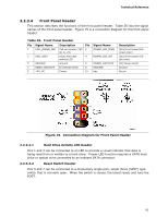
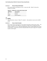
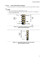
Intel Desktop Board DH61AG Technical Product Specification 2.2.3.4.3 Power/Sleep LED Header Pins 2 and 4 can be connected to a one- or two-color LED. Table 37 shows the possible LED states. Table 37. States for a One-Color Power LED LED State Description Off Power off Blinking Standby Steady Normal operation NOTE The LED behavior shown in Table 37 is default - other patterns may be set via BIOS setup. 2.2.3.4.4 Power Switch Header Pins 6 and 8 can be connected to a front panel momentary-contact power switch. The switch must pull the SW_ON# pin to ground for at least 50 ms to signal the power supply to switch on or off. (The time requirement is due to internal debounce circuitry on the board.) At least two seconds must pass before the power supply will recognize another on/off signal. 62
-
 1
1 -
2
-
3
-
4
-
5
-
6
-
7
-
8
-
9
-
10
-
11
-
12
-
13
-
14
-
15
-
16
-
17
-
18
-
19
-
20
-
21
-
22
-
23
-
24
-
25
-
26
-
27
-
28
-
29
-
30
-
31
-
32
-
33
-
34
-
35
-
36
-
37
-
38
-
39
-
40
-
41
-
42
-
43
-
44
-
45
-
46
-
47
-
48
-
49
-
50
-
51
-
52
-
53
-
54
-
55
-
56
-
 57
57 -
 58
58 -
 59
59 -
 60
60 -
 61
61 -
 62
62 -
 63
63 -
 64
64 -
 65
65 -
 66
66 -
 67
67 -
68
-
69
-
70
-
71
-
72
-
73
-
74
-
75
-
76
-
77
-
78
-
79
-
80
-
81
-
82
-
83
-
84
-
85
-
86
-
87
-
88
-
89
-
90
-
91
-
92
-
93
-
94
-
95
-
96
-
97
-
98
-
99
-
100
-
101
-
102
-
103
-
104
-
105
-
106
-
107
-
108
 |
 |
