Intel DH61AG Technical Product Specification - Page 9

Error Messages and Beep Codes, Regulatory Compliance and Battery Disposal Information, s

Page 9 highlights

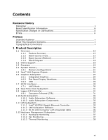
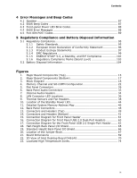
Contents 4 Error Messages and Beep Codes 4.1 Speaker 87 4.2 BIOS Beep Codes 87 4.3 Front-panel Power LED Blink Codes 88 4.4 BIOS Error Messages 88 4.5 Port 80h POST Codes 89 5 Regulatory Compliance and Battery Disposal Information 5.1 Regulatory Compliance 95 5.1.1 Safety Standards 95 5.1.2 European Union Declaration of Conformity Statement 96 5.1.3 Product Ecology Statements 97 5.1.4 EMC Regulations 99 5.1.5 ENERGY STAR* 5.0, e-Standby, and ErP Compliance 102 5.1.6 Regulatory Compliance Marks (Board Level 103 5.2 Battery Disposal Information 104 Figures 1. Major Board Components (Top 15 2. Major Board Components (Bottom 17 3. Block Diagram 18 4. Memory Channel and SO-DIMM Configuration 22 5. Flat Panel Connectors 26 6. Back Panel Audio Connectors 33 7. Internal Audio Headers 34 8. LAN Connector LED Locations 36 9. Thermal Sensors and Fan Headers 38 10. Location of the Standby Power LED 44 11. Detailed System Memory Address Map 46 12. Back Panel Connectors 48 13. Connectors and Headers (Top 49 14. Connectors and Headers (Bottom 51 15. Connection Diagram for Front Panel Header 61 16. Connection Diagram for Front Panel USB 2.0 Dual-Port Headers 63 17. Connection Diagram for the Front Panel USB 2.0 Single-Port Header ....... 63 18. Half-Height Back Panel I/O Shield 65 19. Standard-Height Back Panel I/O Shield 66 20. Location of the Jumper Block 67 21. Board Dimensions 69 22. 3D View of Intel Desktop Board DH61AG 70 23. Localized High Temperature Zones 74 ix

  • 1
  • 2
  • 3
  • 4
  • 5
  • 6
  • 7
  • 8
  • 9
  • 10
  • 11
  • 12
  • 13
  • 14
  • 15
  • 16
  • 17
  • 18
  • 19
  • 20
  • 21
  • 22
  • 23
  • 24
  • 25
  • 26
  • 27
  • 28
  • 29
  • 30
  • 31
  • 32
  • 33
  • 34
  • 35
  • 36
  • 37
  • 38
  • 39
  • 40
  • 41
  • 42
  • 43
  • 44
  • 45
  • 46
  • 47
  • 48
  • 49
  • 50
  • 51
  • 52
  • 53
  • 54
  • 55
  • 56
  • 57
  • 58
  • 59
  • 60
  • 61
  • 62
  • 63
  • 64
  • 65
  • 66
  • 67
  • 68
  • 69
  • 70
  • 71
  • 72
  • 73
  • 74
  • 75
  • 76
  • 77
  • 78
  • 79
  • 80
  • 81
  • 82
  • 83
  • 84
  • 85
  • 86
  • 87
  • 88
  • 89
  • 90
  • 91
  • 92
  • 93
  • 94
  • 95
  • 96
  • 97
  • 98
  • 99
  • 100
  • 101
  • 102
  • 103
  • 104
  • 105
  • 106
  • 107
  • 108

Contents
ix
4
Error Messages and Beep Codes
4.1 Speaker
.........................................................................................
87
4.2
BIOS Beep Codes
............................................................................
87
4.3
Front-panel Power LED Blink Codes
....................................................
88
4.4
BIOS Error Messages
.......................................................................
88
4.5
Port 80h POST Codes
.......................................................................
89
5
Regulatory Compliance and Battery Disposal Information
5.1
Regulatory Compliance
.....................................................................
95
5.1.1
Safety Standards
..................................................................
95
5.1.2
European Union Declaration of Conformity Statement
................
96
5.1.3
Product Ecology Statements
...................................................
97
5.1.4
EMC Regulations
..................................................................
99
5.1.5
ENERGY STAR* 5.0, e-Standby, and ErP Compliance
................
102
5.1.6
Regulatory Compliance Marks (Board Level)
............................
103
5.2
Battery Disposal Information
............................................................
104
Figures
1.
Major Board Components (Top)
.........................................................
15
2.
Major Board Components (Bottom)
....................................................
17
3.
Block Diagram
................................................................................
18
4.
Memory Channel and SO-DIMM Configuration
......................................
22
5.
Flat Panel Connectors
.......................................................................
26
6.
Back Panel Audio Connectors
............................................................
33
7.
Internal Audio Headers
.....................................................................
34
8.
LAN Connector LED Locations
............................................................
36
9.
Thermal Sensors and Fan Headers
.....................................................
38
10. Location of the Standby Power LED
....................................................
44
11. Detailed System Memory Address Map
...............................................
46
12. Back Panel Connectors
.....................................................................
48
13. Connectors and Headers (Top)
..........................................................
49
14. Connectors and Headers (Bottom)
.....................................................
51
15. Connection Diagram for Front Panel Header
........................................
61
16. Connection Diagram for Front Panel USB 2.0 Dual-Port Headers
.............
63
17. Connection Diagram for the Front Panel USB 2.0 Single-Port Header
.......
63
18. Half-Height Back Panel I/O Shield
......................................................
65
19. Standard-Height Back Panel I/O Shield
...............................................
66
20. Location of the Jumper Block
.............................................................
67
21. Board Dimensions
...........................................................................
69
22. 3D View of Intel Desktop Board DH61AG
............................................
70
23. Localized High Temperature Zones
.....................................................
74