Intel ISP2150 Quick Start Guide
Intel ISP2150 - Server Platform - 0 MB RAM Manual
 |
UPC - 735858134668
View all Intel ISP2150 manuals
Add to My Manuals
Save this manual to your list of manuals |
Intel ISP2150 manual content summary:
- Intel ISP2150 | Quick Start Guide - Page 1
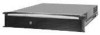
ISP2150 2U Rack Server Platform Quick Start Guide A Guide for Technically Qualified Assemblers of Intel® Identified Subassemblies/ Products Before You Begin FCC Declaration of Conformity 4 Cautions and Warnings ...6 Product Regulation Compliance 7 Safety Compliance...7 Electromagnetic - Intel ISP2150 | Quick Start Guide - Page 2
The ISP2150 2U Rack Server Platform Product Guide can be found at http://channel.intel.com/isp/ Copyright © 2000 Intel Corporation. All rights reserved. No part of this document may be copied, or reproduced in any form, or by any means without prior written consent of Intel. Intel Corporation (Intel - Intel ISP2150 | Quick Start Guide - Page 3
manual. When used near a radio or TV receiver, it may become the cause of radio interference. Read the instructions for correct handling. This equipment has been tested for radio frequency emissions and has been verified to meet CISPR 22 Class B. ISP2150 2U Rack Server Platform Quick Start Guide - Intel ISP2150 | Quick Start Guide - Page 4
and configuring servers. Read and adhere to all warnings, cautions, and notices in this guide and the documentation supplied with the chassis, power supply, and accessory modules. If the instructions for the chassis and power supply are inconsistent with these instructions or the instructions for - Intel ISP2150 | Quick Start Guide - Page 5
Regulation Compliance See the ISP2150 2U Rack Server Platform Product Guide for all applicable safety standards, electromagnetic compatibility (EMC) regulations, and product certification markings. Intended uses: This product was evaluated for use in computer rack cabinets within computer rooms - Intel ISP2150 | Quick Start Guide - Page 6
the purchase of your new Intel® ISP2150 system. This Quick Start introduces you to your new system, guides you through rack kit installation, and helps . The hinging mechanism will guide the bezel into the correct position where it will snap shut. 8 ISP2150 2U Rack Server Platform Quick Start - Intel ISP2150 | Quick Start Guide - Page 7
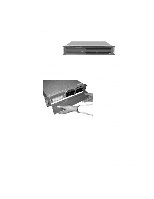
. Installation Follow these instructions to get your sever to the point where you can load an operating system on it. Open the Cover 1. Loosen the three screws on the rear of the system. 2. Pull the cover back and remove it from the chassis. ISP2150 2U Rack Server Platform Quick Start Guide 9 - Intel ISP2150 | Quick Start Guide - Page 8
). With a single-processor configuration, you must install a termination board and termination latch assembly (A) in the empty secondary connector (B) to ensure proper operation of your system. A termination board is provided with your system. 10 ISP2150 2U Rack Server Platform Quick Start Guide - Intel ISP2150 | Quick Start Guide - Page 9
supports 100 MHz PC/100-compliant SDRAM. • Install from 32 MB to 2 GB of unbuffered memory, using up to four single or double-banked DIMMs Or • Install from 32 MB to 2 GB of registered memory, using up to four single or double-banked DIMMs OM09318 ISP2150 2U Rack Server Platform Quick Start Guide - Intel ISP2150 | Quick Start Guide - Page 10
. 6. Repeat the steps to install each DIMM. 7. Ensure that no cables are protruding from the server chassis and then close the server. 8. Connect all external cables and the power cord to the server. 9. Turn on the monitor and then the server. 12 ISP2150 2U Rack Server Platform Quick Start Guide - Intel ISP2150 | Quick Start Guide - Page 11
the screws. 5. Slide the carrier/drive into the chassis with the retention mechanism extended in the open position, then push the arm towards the front of the chassis until the lever tab clicks into the chassis slot indicating that it is closed. ISP2150 2U Rack Server Platform Quick Start Guide 13 - Intel ISP2150 | Quick Start Guide - Page 12
must use the PCI slots on the riser card. Do not use any expansion slots on the server board. 1. Remove the expansion slot cover for the slot you wish to use. Remove the Remove the expansion slot cover (C) for the slot you wish to use. OM09325 14 ISP2150 2U Rack Server Platform Quick Start Guide - Intel ISP2150 | Quick Start Guide - Page 13
or switches according to the manufacturer's instructions. 4. Hold board by its top edge guide back into place. The back edge of the card should be held in place by the rail of the card guide. 6. Install the cover retention bracket and thumbscrew. ISP2150 2U Rack Server Platform Quick Start Guide - Intel ISP2150 | Quick Start Guide - Page 14
drive in the section "Re-Installing the OM09319 Diskette Drive". 8. Insert the recessed retention screws (C) through the access holes in the top of the drive bay housing. 9. Insert the retention screw (D) on the front of the chassis. 16 ISP2150 2U Rack Server Platform Quick Start Guide - Intel ISP2150 | Quick Start Guide - Page 15
to the manufacturer's specifications. Close the Cover 1. Place the cover on the chassis and slide it forwards as far as possible. The sides and front of the cover fit inside the chassis. 2. Tighten the three screws on the rear of the chassis. ISP2150 2U Rack Server Platform Quick Start Guide 17 - Intel ISP2150 | Quick Start Guide - Page 16
of the system with the bracket flange flush with the front panel. 2. Attach the rear support washer to the system. The system also comes with two support washers (C). Mount one on each side towards the rear panel of the system. B A C OM09334 18 ISP2150 2U Rack Server Platform Quick Start Guide - Intel ISP2150 | Quick Start Guide - Page 17
support washers as rollers. A C 5. Mount the front bracket to the cabinet. To complete the installation, bolt the system's front brackets to the cabinet using the mounting bolts (A) supplied by the cabinet manufacturer. A B OM09336 A OM09346 ISP2150 2U Rack Server Platform Quick Start Guide - Intel ISP2150 | Quick Start Guide - Page 18
. A 2. Mount the bracket to the center channel of the relay rack. To complete the installation, bolt the system's front brackets to the cabinet using the mounting bolts (A) supplied by the cabinet manufacturer. A B OM09335 A OM09347 20 ISP2150 2U Rack Server Platform Quick Start Guide - Intel ISP2150 | Quick Start Guide - Page 19
finger tab (D) is facing outward. With the holes in the chassis (C) aligned with the holes in the rail, fasten the rail using the largest screws (B) supplied with the rail kit. D D A B C A B C OM09132 D OM09133 ISP2150 2U Rack Server Platform Quick Start Guide 21 - Intel ISP2150 | Quick Start Guide - Page 20
is facing up (C). Use eight mounting screws (D) D provided by the manufacturer of the cabinet rack. In the illustration to the right, the left photo (A) shows the left- front bracket the A brackets yet.) OM09145 C D B OM09142 continued 22 ISP2150 2U Rack Server Platform Quick Start Guide - Intel ISP2150 | Quick Start Guide - Page 21
system back and forth in the rail brackets. When you have centered the rails in the bracket, tighten the fastening bolts and nuts. B A B A C OM09138 OM09144 ISP2150 2U Rack Server Platform Quick Start Guide 23 - Intel ISP2150 | Quick Start Guide - Page 22
chassis back. 11. With the chassis fully inserted into the cabinet rack, you can easily access both the front and rear of the system. The photo to the right shows the system from the rear fully inserted into the cabinet. OM09141 A B OM09143 24 ISP2150 2U Rack Server Platform Quick Start Guide - Intel ISP2150 | Quick Start Guide - Page 23
B. Sleep button C. Reset button D. Power LED E. NIC activity LED F. Fail LED G. Disk activity/fail LEDs H. Hard drive bay I. Hard drive eject lever J. CDROM drive bay K. Diskette eject button L. Diskette drive M. Diskette activity LED OM09320 ISP2150 2U Rack Server Platform Quick Start Guide 25 - Intel ISP2150 | Quick Start Guide - Page 24
A. Mouse connector B. Parallel port connector C. PCI expansion slots D. AC input power connector E. Power supply fault indicator F. Video connector G. USB connectors H. RJ45 network connector I. Serial connection. Not linked to network. 26 ISP2150 2U Rack Server Platform Quick Start Guide - Intel ISP2150 | Quick Start Guide - Page 25
Jumpers Nine 3-pin jumper blocks that control various configuration options, as shown in the figure below. Refer to the ISP2150 2U Rack Server Platform Product Guide for more information. WOL ENABLE J5A2 1 BMC WR EN J4J2 1 J3J1 BIOS WR EN J2J1 BMC FRC UP INT DET RCVRY BOOT FRB PSWD CLR 1 - Intel ISP2150 | Quick Start Guide - Page 26
to use the WOL feature, your power supply must provide 0.8 A of +5 V Standby current. If it does not, your server board may not boot. Move the WOL Enable jumper to the Disabled position if your power supply does not provide the required current. 28 ISP2150 2U Rack Server Platform Quick Start Guide - Intel ISP2150 | Quick Start Guide - Page 27
Ultra wide SCSI connector S. Server Monitor Module (SMM) connector T. External Wake on LAN connector U. Ultra2/LVD SCSI connector V. Hard drive LED connector W. Intelligent Chassis Management Serial port connector II. Mouse/keyboard connectors ISP2150 2U Rack Server Platform Quick Start Guide 29 - Intel ISP2150 | Quick Start Guide - Page 28
Getting Help World Wide Web Support for this product may be found at the following URL: Une assistance pour ce produit est la siguiente dirección URL: O suporte para este produto pode ser encontrado no seguinte URL: http://www.intel.com/isp/ 30 ISP2150 2U Rack Server Platform Quick Start Guide
-
 1
1 -
 2
2 -
 3
3 -
 4
4 -
 5
5 -
 6
6 -
 7
7 -
8
-
9
-
10
-
11
-
12
-
13
-
14
-
15
-
16
-
17
-
18
-
19
-
20
-
21
-
22
-
23
-
24
-
25
-
26
-
27
-
28
 |
 |

ISP2150 2U Rack Server Platform
Quick Start Guide
A Guide for Technically Qualified Assemblers of Intel
®
Identified
Subassemblies/ Products
Before You Begin
FCC Declaration of Conformity
..................................................................................................
4
Cautions and Warnings
...............................................................................................................
6
Product Regulation Compliance
..................................................................................................
7
Safety Compliance
......................................................................................................................
7
Electromagnetic Compatibility (EMC)
.......................................................................................
7
ISP2150
Opening and Closing the Front Bezel
.........................................................................................
8
Locking and Unlocking the Front Bezel
.....................................................................................
9
Attaching and Removing the Front Bezel
...................................................................................
9
Installation
Open the Cover
...........................................................................................................................
9
Installing a Microprocessor
.......................................................................................................
10
Installing Memory
.....................................................................................................................
11
Installing a Hard Drive
..............................................................................................................
13
Installing Add-in Cards
.............................................................................................................
14
Installing a Slim-Line CD-ROM Drive
.....................................................................................
16
Removing a Diskette Drive
.......................................................................................................
17
Re-Installing a Diskette Drive
...................................................................................................
17
Close the Cover
.........................................................................................................................
17
Installing the Front Bracket and Racking Your System
............................................................
18
Installing the Front Bracket in a Cabinet
...................................................................................
18
Installing the Front Bracket in a Center-Mount, Relay Rack
....................................................
20
Installing the Rail Kit and Racking Your System (Optional Accessory)
...................................
21
Technical Reference
Front Panel Controls and Indicators
..........................................................................................
25
Back Panel Connectors
.......................................................................................................... ...
26
Jumpers
........................................................................................................................ .............
27
Server Board Components
........................................................................................................
29
Getting Help
.......................................................................................................................................
30
Order Number:
A13687-001