Intel ISP2150 Quick Start Guide - Page 20
One pair
 |
UPC - 735858134668
View all Intel ISP2150 manuals
Add to My Manuals
Save this manual to your list of manuals |
Page 20 highlights
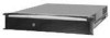
4. Here is a combination side and rear view of the chassis after the right inside rail has been attached. 5. Locate the front and rear rail brackets A B for one side of the rail kit. One pair (A and B) exists for each side of the cabinet rack. C 6. Attach all four rail brackets to the cabinet rack. Be sure that the sharper angled side of each bracket is facing up (C). Use eight mounting screws (D) D provided by the manufacturer of the cabinet rack. In the illustration to the right, the left photo (A) shows the left- front bracket attached to the cabinet, while the right photo (B) shows the left-rear bracket. (The photo shows the rails inside the brackets. You should not have the rails attached inside the A brackets yet.) OM09145 C D B OM09142 continued 22 ISP2150 2U Rack Server Platform Quick Start Guide
-
 1
1 -
2
-
3
-
4
-
5
-
6
-
7
-
8
-
9
-
10
-
11
-
12
-
13
-
14
-
 15
15 -
 16
16 -
 17
17 -
 18
18 -
 19
19 -
 20
20 -
 21
21 -
 22
22 -
 23
23 -
 24
24 -
 25
25 -
26
-
27
-
28
 |
 |
