Intel MFS5520VI User Guide
Intel MFS5520VI - Multi-Flex Server Compute Module Manual
 |
UPC - 735858209250
View all Intel MFS5520VI manuals
Add to My Manuals
Save this manual to your list of manuals |
Intel MFS5520VI manual content summary:
- Intel MFS5520VI | User Guide - Page 1
Intel® Compute Module MFS5520VI User Guide A Guide for Technically Qualified Assemblers of Intel® Identified Subassemblies/ Products Intel Order Number E60459-006 - Intel MFS5520VI | User Guide - Page 2
Intel assumes no liability whatsoever, and Intel disclaims any express or implied warranty, relating to sale and/or use of Intel® products including liability or warranties the system integrator that chooses not to use Intel developed server building blocks to consult vendor datasheets and operating - Intel MFS5520VI | User Guide - Page 3
BIOS Setup Utility as well as update the compute module firmware using the Intel® Modular Server Control UI and the latest Intel® Modular Server System MFSYS25/ MFSYS35 Unified Firmware Update (UFU). Chapter 4 provides information to assist you in troubleshooting the Intel® Compute Module MFS5520VI - Intel MFS5520VI | User Guide - Page 4
iv Intel® Compute Module MFS5520VI User Guide - Intel MFS5520VI | User Guide - Page 5
las declaraciones de seguridad y precaución de este documento antes de realizar cualquiera de las instrucciones. Vea Intel® Server Boards and Server Chassis Safety Information en http://support.intel.com/support/motherboards/server/sb/cs-010770.htm. Intel® Compute Module MFS5520VI User Guide v - Intel MFS5520VI | User Guide - Page 6
whenever you remove the compute module enclosure cover to access components inside the chassis. Only a technically qualified person should maintain or configure the chassis. Heed safety instructions: Before working with your server product, whether you are using this guide or any other resource - Intel MFS5520VI | User Guide - Page 7
...16 Installing or Replacing a Processor 17 Installing a Processor ...17 Replacing a Processor ...25 Installing and Removing Memory Modules 33 Supported Memory ...33 Memory Map and Population Rules 33 Installing DIMMs ...35 Removing DIMMs ...38 Intel® Compute Module MFS5520VI User Guide vii - Intel MFS5520VI | User Guide - Page 8
89 Clearing the CMOS ...92 BIOS Recovery Procedure 93 Troubleshooting ...95 First Steps Checklist ...95 Hardware Diagnostic Testing 96 Specific Problems and Corrective Actions 96 Power 102 Latin America ...102 B Product Regulatory Requirements 105 viii Intel® Compute Module MFS5520VI User Guide - Intel MFS5520VI | User Guide - Page 9
110 Other Hazards ...110 Deutsch ...111 Sicherheitshinweise für den Server 111 Sicherheitshinweise und Vorsichtsmaßnahmen 111 Zielbenutzer der Anwendung 112 Standortauswahl al sistema 122 Descarga electrostática (ESD 123 Otros peligros ...124 Intel® Compute Module MFS5520VI User Guide ix - Intel MFS5520VI | User Guide - Page 10
D Installation/Assembly Safety Instructions 131 English ...131 Deutsch ...133 Français ...136 Español ...138 Italiano ...140 x Intel® Compute Module MFS5520VI User Guide - Intel MFS5520VI | User Guide - Page 11
List of Figures Figure 1. Intel® Compute Module MFS5520VI 1 Figure 2. Server Board ...2 Figure 3. Component and Connector Locations 4 Figure 4. Configuration Jumper Locations 5 Figure 5. . Removing Standoffs 48 Figure 42. CMOS Battery Location 50 Intel® Compute Module MFS5520VI User Guide xi - Intel MFS5520VI | User Guide - Page 12
61 Figure 47. Advanced Memory Configuration Screen 64 Figure 48. Memory RAS and Performance Configuration Server Management Screen 76 Figure 56. Server Management - Console Redirection Enabled Screen 79 Figure 57. Server BIOS Recover Jumper 94 xii Intel® Compute Module MFS5520VI User Guide - Intel MFS5520VI | User Guide - Page 13
PCI Configuration Details 72 Table 10. Security Screen Details 75 Table 11. Server Management Screen Details 77 Table 12. Server Management Console Redirection Details 80 Table 13. Boot Options Details 83 Table 14. Exit Screen Details 86 Intel® Compute Module MFS5520VI User Guide xiii - Intel MFS5520VI | User Guide - Page 14
xiv Intel® Compute Module MFS5520VI User Guide - Intel MFS5520VI | User Guide - Page 15
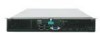
as provides illustrations showing the location of important components and connections on the compute module. The Intel® Compute Module MFS5520VI is shown in the following pictures. 1 I/O 2 1 2 ID Figure 1. Intel® Compute Module MFS5520VI AF003075 Intel® Compute Module MFS5520VI User Guide 1 - Intel MFS5520VI | User Guide - Page 16
Figure 2. Server Board 2 Intel® Compute Module MFS5520VI User Guide - Intel MFS5520VI | User Guide - Page 17
following table summarizes the major features of the compute module. Table 1. Compute Module Features Feature Processor Memory Chipset Video LAN Hard Drive Server Management Description Support for one or two Intel® Xeon® Processors 5500 Series or two Intel® Xeon® Processor 5600 Series in FC-LGA - Intel MFS5520VI | User Guide - Page 18
Connector H Midplane Guide Pin Receptacle I CPU 1 DIMM Slots J CPU 2 Socket K Power/Fault LEDs L Power Switch M Activity and ID LEDs N Video Connector O USB Ports 2 and 3 P USB Ports 0 and 1 Q CMOS Battery Figure 3. Component and Connector Locations 4 Intel® Compute Module MFS5520VI User Guide - Intel MFS5520VI | User Guide - Page 19
BIOS Recover 3 Boot from Emergency 2 BIOS Image Default J9B9 PASSWORD Clear 32 Clear Default Password J9A3 CMOS Clear 32 Clear Default CMOS J9A4 BMC Force Update 32 Enabled Default Disabled J9A5 Figure 4. Configuration Jumper Locations AF003078 Intel® Compute Module MFS5520VI User Guide - Intel MFS5520VI | User Guide - Page 20
pins are jumpered, the compute module boots from the emergency BIOS image. These pins should compute module into the chassis. J9A5: BMC Force 1-2 Update 2-3 BMC Firmware Force Update Mode - Disabled (Default) BMC Firmware Force Update Mode - Enabled 6 Intel® Compute Module MFS5520VI User Guide - Intel MFS5520VI | User Guide - Page 21
Indicators Front Panel Indicators The Intel® Compute Module MFS5520VI includes a number of diagnostic LEDs on the front of the compute module to aid in troubleshooting. The following table lists does not have an ID LED) Double blink = Degraded state Intel® Compute Module MFS5520VI User Guide 7 - Intel MFS5520VI | User Guide - Page 22
up to 12 DIMMs with dual-processor sockets. The compute module supports DDR3 1066 and DDR3 1333 memory technologies and supports both registered DIMMs (RDIMMs) and unbuffered DIMMs (UDIMMs). RDIMMs must be ECC only, while UDIMMs can be ECC or non-ECC. 8 Intel® Compute Module MFS5520VI User Guide - Intel MFS5520VI | User Guide - Page 23
) plus all other modules in the chassis. Three power supplies support four to six compute modules (in any slot) plus all other modules in the chassis. Any additional power supplies above the minimum required (based on configuration) provide redundancy. Intel® Compute Module MFS5520VI User Guide 9 - Intel MFS5520VI | User Guide - Page 24
Start User's Guide Available in the product box or for download at: http://www.intel.com/support/motherboards/server/mfs5520vi/ Intel®Compute Module MFS5520VI Technical Product Specification Available at: http://www.intel.com/support/motherboards/server/mfs5520vi/ Intel®Modular Server System MFSYS25 - Intel MFS5520VI | User Guide - Page 25
For instructions and information refer to the Intel® Modular Server System MFSYS25/MFSYS35 User Guide Available at: http://www.intel.com/support/motherboards/server/mfsys25/ Intel® System Management Software Available at: http://www.intel.com/go/servermanagement/ Intel® Compute Module MFS5520VI - Intel MFS5520VI | User Guide - Page 26
12 Intel® Compute Module MFS5520VI User Guide - Intel MFS5520VI | User Guide - Page 27
the instructions included with the hot-swap component. Removing and Installing an Intel® Compute Module MFS5520VI Removing a Compute Module from the Chassis To remove a compute module from the chassis, follow these steps: 1. Observe the safety and ESD information at the beginning of this manual and - Intel MFS5520VI | User Guide - Page 28
. 2. If the compute module is installed in a chassis, remove it. For instructions, see "Removing a Compute Module from the Chassis" on page 13. 3. Carefully lay the compute module down on a flat, non-conductive surface, with the cover side up. 14 Intel® Compute Module MFS5520VI User Guide - Intel MFS5520VI | User Guide - Page 29
in Figure 6). 5. Lift the top cover up and off the compute module (see letter "C" in Figure 6) . Caution: Always install the top cover before installing the compute module into a chassis. C A B 1 I/O 2 1 2 ID Figure 6. Removing Top Cover AF003088 Intel® Compute Module MFS5520VI User Guide 15 - Intel MFS5520VI | User Guide - Page 30
and that no loose tools or parts are inside the compute module. 3. Slide the top cover forward to the closed position until the retention latch fully engages (see letter "B" in Figure 7). A B 1 I/O 2 1 2 ID Figure 7. Installing Top Cover AF003089 16 Intel® Compute Module MFS5520VI User Guide - Intel MFS5520VI | User Guide - Page 31
. Removing Components 2. If the compute module is installed in a chassis, remove it. For instructions, see "Removing a Compute Module from the Chassis" on page 13. 3. Remove the top cover. For instructions, see "Removing the Top Cover" on page 14. Intel® Compute Module MFS5520VI User Guide 17 - Intel MFS5520VI | User Guide - Page 32
4. Remove the processor air duct (see Figure 8). 1 I/O 2 1 2 ID Figure 8. Removing Processor Air Duct AF003080 18 Intel® Compute Module MFS5520VI User Guide - Intel MFS5520VI | User Guide - Page 33
for the first time. Note: If you are installing only a single processor on your server board, do not remove the heatsink and spacer over the second processor. 5. Loosen the Discard to Install CPU This Side Up AF003161 Figure 9. Removing the Heatsink Intel® Compute Module MFS5520VI User Guide 19 - Intel MFS5520VI | User Guide - Page 34
pins; they are very sensitive and easily damaged. Note: Retain the protective socket cover for use when removing a processor that will not be replaced. 20 Intel® Compute Module MFS5520VI User Guide - Intel MFS5520VI | User Guide - Page 35
the processor with the socket so that the processor cutouts match the two socket pins, and insert the processor into the socket (see Figure 14). Intel® Compute Module MFS5520VI User Guide 21 - Intel MFS5520VI | User Guide - Page 36
Figure 16. The heatsink fins must be positioned as shown to provide correct airflow through the system. Airflow goes from front-to-back of the compute module. 22 Intel® Compute Module MFS5520VI User Guide - Intel MFS5520VI | User Guide - Page 37
so as to provide correct airflow through the compute module. 20. Set the heatsink over the processor, lining up Compute Module Front CPU 1 Socket AF003122 Figure 16. Installing the Heatsink Reinstalling components 22. Reinstall the processor air duct. Intel® Compute Module MFS5520VI User Guide - Intel MFS5520VI | User Guide - Page 38
Processor Air Duct 23. Reinstall the top cover. For instructions, see "Installing the Top Cover" on page 16. 24. Reinstall the server compute module in the chassis. For instructions, see "Installing a Compute Module into the Chassis" on page 14. 24 Intel® Compute Module MFS5520VI User Guide - Intel MFS5520VI | User Guide - Page 39
a Compute Module from the Chassis" on page 13. 3. Remove the top cover. For instructions, see "Removing the Top Cover" on page 14. 4. Remove the processor air duct (see Figure 18). 1 I/O 2 1 2 ID Figure 18. Removing Processor Air Duct AF003080 Intel® Compute Module MFS5520VI User Guide 25 - Intel MFS5520VI | User Guide - Page 40
away from the socket to release it (see letter "A" in Figure 20). 9. Rotate the lever open all the way (see letter "B" in Figure 20). 26 Intel® Compute Module MFS5520VI User Guide - Intel MFS5520VI | User Guide - Page 41
). B A AF003096 Figure 21. Opening the Load Plate 12. Remove the processor. Note: Do not touch the socket pins; they are very sensitive and easily damaged. Intel® Compute Module MFS5520VI User Guide 27 - Intel MFS5520VI | User Guide - Page 42
A AF003097 Figure 22. Removing the Processor 28 Intel® Compute Module MFS5520VI User Guide - Intel MFS5520VI | User Guide - Page 43
. Close the socket lever completely and ensure that the load plate tab engages under the socket lever when fully closed (see letter "B" in Figure 25). Intel® Compute Module MFS5520VI User Guide 29 - Intel MFS5520VI | User Guide - Page 44
2 should be oriented in a reverse direction so as to provide correct airflow through the compute module. 19. Set the heatsink over the processor, lining up the four captive screws with the four posts tightened upto a maximum of 8 inch-lbs torque. 30 Intel® Compute Module MFS5520VI User Guide - Intel MFS5520VI | User Guide - Page 45
3 2 Air Flow 1 4 TIM Front CPU 1 Socket AF002841 Figure 26. Reinstalling Heatsink Intel® Compute Module MFS5520VI User Guide 31 - Intel MFS5520VI | User Guide - Page 46
Processor Air Duct 22. Reinstall the top cover. For instructions, see "Installing the Top Cover" on page 16. 23. Reinstall the server compute module in the chassis. For instructions, see "Installing a Compute Module into the Chassis" on page 14. 32 Intel® Compute Module MFS5520VI User Guide - Intel MFS5520VI | User Guide - Page 47
memory in Channel D through Channel F. However, platform performance suffers latency due to remote memory. • The memory operational mode is configurable at the channel level. Two modes are supported: Independent Channel Mode and Mirrored Channel Mode. Intel® Compute Module MFS5520VI User Guide - Intel MFS5520VI | User Guide - Page 48
set of parameters and RAS still functions. • DDR3 DIMMs on adjacent slots on the same channel do not need to be identical. • For the Mirrored Channel mode, the memory empty, the BIOS disables the memory in the third channel of each processor socket. 34 Intel® Compute Module MFS5520VI User Guide - Intel MFS5520VI | User Guide - Page 49
the compute module switches to the Independent Channel Mode. Installing DIMMs DIMM slots are numbered as follows: DIMM B2 DIMM A1 DIMM A2 DIMM B1 DIMM C2 DIMM C1 DIMM F1 DIMM F2 DIMM E1 DIMM D2 DIMM D1 DIMM E2 Figure 29. DIMM Slot Order AF003098 Intel® Compute Module MFS5520VI User Guide 35 - Intel MFS5520VI | User Guide - Page 50
information at the beginning of this manual and in the appendices. 2. If the compute module is installed in a chassis, remove it. For instructions, see "Removing a Compute Module from the Chassis" on page 13 into place (see letter "C" in Figure 31). 36 Intel® Compute Module MFS5520VI User Guide - Intel MFS5520VI | User Guide - Page 51
F1 DIMM F2 DIMM E1 DIMM D2 DIMM D1 DIMM E2 Figure 31. Installing DIMMs 13. Reinstall the processor air duct (see Figure 32). AF003099 Intel® Compute Module MFS5520VI User Guide 37 - Intel MFS5520VI | User Guide - Page 52
manual and in the appendices. 2. If the compute module is installed in a chassis, remove it. For instructions, see "Removing a Compute Module from the Chassis" on page 13. 3. Remove the top cover. For instructions, see "Removing the Top Cover" on page 14. 38 Intel® Compute Module MFS5520VI User - Intel MFS5520VI | User Guide - Page 53
34). This slightly lifts the DIMM from its socket. 7. Holding the DIMM by the edges, remove it from the socket (see letter "B" in Figure 34). Intel® Compute Module MFS5520VI User Guide 39 - Intel MFS5520VI | User Guide - Page 54
Important: Store the removed DIMM in an anti-static package. DIMM B2 DIMM A1 DIMM A2 DIMM B1 DIMM C2 DIMM C1 E B D A DIMM F1 DIMM F2 DIMM E1 DIMM D2 DIMM D1 DIMM E2 Figure 34. Removing DIMMs AF003100 40 Intel® Compute Module MFS5520VI User Guide - Intel MFS5520VI | User Guide - Page 55
Processor Air Duct 9. Reinstall the top cover. For instructions, see "Installing the Top Cover" on page 16. 10. Reinstall the server compute module in the chassis. For instructions, see "Installing a Compute Module into the Chassis" on page 14. Intel® Compute Module MFS5520VI User Guide 41 - Intel MFS5520VI | User Guide - Page 56
instructions, see "Removing the Top Cover" on page 14. 4. Holding the mezzanine card by its edges, remove it from the packaging. 5. Remove the protective connector cover from the mezzanine card. 6. Locate the mezzanine card connectors on the server board. 42 Intel® Compute Module MFS5520VI User - Intel MFS5520VI | User Guide - Page 57
7. Using a Phillips* screwdriver, remove four screws from the server board (see Figure 36). 1 I/O 2 1 2 ID Figure 36. Removing Screws from Server Board AF003090 Intel® Compute Module MFS5520VI User Guide 43 - Intel MFS5520VI | User Guide - Page 58
8. Using a 1/4-inch nut driver, install the four standoffs that shipped with the mezzanine card (see Figure 37). 1 I/O 2 1 2 ID Figure 37. Installing Standoffs for Mezzanine Card AF003082 44 Intel® Compute Module MFS5520VI User Guide - Intel MFS5520VI | User Guide - Page 59
and resting on the standoff supports. 11. Secure the mezzanine instructions, see "Installing the Top Cover" on page 16. 13. Reinstall the server compute module in the chassis. For instructions, see "Installing a Compute Module into the Chassis" on page 14. Intel® Compute Module MFS5520VI User Guide - Intel MFS5520VI | User Guide - Page 60
at the beginning of this manual and in the appendices. 2. If the compute module is installed in a chassis, remove it. For instructions, see "Removing a Compute Module from the Chassis" on 2 ID Figure 39. Removing Screws from Mezzanine Card AF003091 46 Intel® Compute Module MFS5520VI User Guide - Intel MFS5520VI | User Guide - Page 61
6. Holding the mezzanine card by its edges, gently lift it from the connectors and store it in an anti-static package (see Figure 40). Mezzanine Card 1 I/O 2 1 2 ID Figure 40. Removing Mezzanine Card AF003092 Intel® Compute Module MFS5520VI User Guide 47 - Intel MFS5520VI | User Guide - Page 62
vacated by the standoffs. 9. Reinstall the top cover. For instructions, see "Installing the Top Cover" on page 16. 10. Reinstall the server compute module in the chassis. For instructions, see "Installing a Compute Module into the Chassis" on page 14. 48 Intel® Compute Module MFS5520VI User Guide - Intel MFS5520VI | User Guide - Page 63
manual and in the appendices. 2. If the compute module is installed in a chassis, remove it. For instructions, see "Removing a Compute Module from the Chassis" on page 13. 3. Remove the top cover. For instructions, see "Removing the Top Cover" on page 14. Intel® Compute Module MFS5520VI User Guide - Intel MFS5520VI | User Guide - Page 64
it in the battery socket. 9. Reinstall the top cover. For instructions, see "Installing the Top Cover" on page 16. 10. Reinstall the server compute module in the chassis. For instructions, see "Installing a Compute Module into the Chassis" on page 14 50 Intel® Compute Module MFS5520VI User Guide - Intel MFS5520VI | User Guide - Page 65
11. Run the BIOS setup to restore the configuration settings to the RTC. Intel® Compute Module MFS5520VI User Guide 51 - Intel MFS5520VI | User Guide - Page 66
52 Intel® Compute Module MFS5520VI User Guide - Intel MFS5520VI | User Guide - Page 67
the Intel® Modular Server Control UI or by manually pressing the compute module power button. 3. Press the function key when the below message is displayed during boot time. Press to enter SETUP The message above is displayed after POST completes the memory test either below the BIOS - Intel MFS5520VI | User Guide - Page 68
selection bar is located at the top of the BIOS Setup Utility screen. It displays the major menu selections current selection. B Setup Item List The Setup Item List is a set of controllable and informational items. Each item in the list occupies the Intel® Compute Module MFS5520VI User Guide - Intel MFS5520VI | User Guide - Page 69
can use in the BIOS Setup menus. Table set to their default values. If "No" is selected and the Enter key is pressed, or if the ESC key is pressed, the user is returned to where they were before F9 was pressed without affecting any existing field values. Intel® Compute Module MFS5520VI User Guide - Intel MFS5520VI | User Guide - Page 70
pressed, or the ESC key is pressed, the user is returned to where they were before F10 was pressed without affecting any existing values. 56 Intel® Compute Module MFS5520VI User Guide - Intel MFS5520VI | User Guide - Page 71
appear in bold on the BIOS Setup screen. The bold text in this document is to serve as a reference point. • Changes (except Date and Time) made in the Setup Utility are not applied until they have been saved and the compute module has been rebooted. Intel® Compute Module MFS5520VI User Guide 57 - Intel MFS5520VI | User Guide - Page 72
Main The Main screen is the first screen that appears when the BIOS Setup is entered, unless an error has occurred. If an error has occurred, the Error Manager screen is displayed instead. Figure 44. Main Screen 58 Intel® Compute Module MFS5520VI User Guide - Intel MFS5520VI | User Guide - Page 73
are in 24-hour format. Use the [Enter] or [Tab] key to select the next field. Use the [+] or [-] key to modify the selected field. Intel® Compute Module MFS5520VI User Guide 59 - Intel MFS5520VI | User Guide - Page 74
menu. Processor Configuration The Processor Configuration screen allows you to view detailed information for each installed processor as well as configure several processor options. 60 Intel® Compute Module MFS5520VI User Guide - Intel MFS5520VI | User Guide - Page 75
To access this screen from the Main screen, press the right arrow key until the Advanced menu option is selected then select Processor Configuration from the Advanced menu.. Figure 46. Advanced Processor Configuration Screen Intel® Compute Module MFS5520VI User Guide 61 - Intel MFS5520VI | User Guide - Page 76
® Hyper-Threading Technology allows multi threaded software applications to execute threads in parallel within each processor. Contact your OS vendor regarding OS support of this feature. Enable 1, 2, or all cores of the installed processor packages. 62 Intel® Compute Module MFS5520VI User Guide - Intel MFS5520VI | User Guide - Page 77
, and Serviceability) and view memory performance information and settings. To access this screen from the Main screen press the right arrow key until the Advanced menu option is selected then select Memory Configuration from the Advanced menu. Intel® Compute Module MFS5520VI User Guide 63 - Intel MFS5520VI | User Guide - Page 78
. Figure 47. Advanced Memory Configuration Screen 64 Intel® Compute Module MFS5520VI User Guide - Intel MFS5520VI | User Guide - Page 79
and Serviceability) and Performance Configuration screen displays current memory performance information and settings. Under capabilities, this screen displays whether memory mirroring is possible (Yes / No) and allows the user to enable or disable NUMA optimization. Intel® Compute Module MFS5520VI - Intel MFS5520VI | User Guide - Page 80
enable or disable the SAS controller. By default, the SAS controller is set to [Enabled]. This enables the compute module to access the system storage. If the SAS controller is set to [Disabled], the compute module will not be able to access storage. 66 Intel® Compute Module MFS5520VI User Guide - Intel MFS5520VI | User Guide - Page 81
the Network Serial Console and the Debug Serial Port, the user can modify the following settings: • Enable or Disable the serial port (Network Serial Console or Debug Serial Port) • Select the base I/O address • Select the interrupt request (IRQ) line Intel® Compute Module MFS5520VI User Guide 67 - Intel MFS5520VI | User Guide - Page 82
and press .. Figure 50. Advanced Serial Port Configuration Screen USB Configuration The USB Configuration screen allows you to configure the USB controller options. 68 Intel® Compute Module MFS5520VI User Guide - Intel MFS5520VI | User Guide - Page 83
To access this screen from the Main screen press the right arrow key until the Advanced menu is selected then press the down or up arrow key until USB Configuration is highlighted and press . Figure 51. Advanced USB Configuration Screen Intel® Compute Module MFS5520VI User Guide 69 - Intel MFS5520VI | User Guide - Page 84
. When enabled on-board USB ports are enabled to support USB 2.0 mode. Contact your OS vendor regarding OS support of this feature. PCI Configuration The PCI Configuration Screen allows you to configure the memory usage and on-board NIC controllers. 70 Intel® Compute Module MFS5520VI User Guide - Intel MFS5520VI | User Guide - Page 85
To access this screen from the Main screen press the right arrow key until the Advanced menu is selected then press the down or up arrow key to highlight PCI Configuration and press .. Figure 52. Advanced PCI Configuration Screen Intel® Compute Module MFS5520VI User Guide 71 - Intel MFS5520VI | User Guide - Page 86
Help Text If enabled, BIOS maximizes usage of memory below 4 GB for Intel® Compute Module MFS5520VI. Specifically the System Acoustics and Performance Configuration screen allows the user to set the BIOS overrides that selection if the system can support CLTT Intel® Compute Module MFS5520VI User Guide - Intel MFS5520VI | User Guide - Page 87
Acoustics and Performance Configuration Screen Security The Security screen allows you to enable and set the user and administrative passwords. This screen also allows you to enable and activate the Trusted Platform Module (TPM) security settings. Intel® Compute Module MFS5520VI User Guide 73 - Intel MFS5520VI | User Guide - Page 88
To access this screen from the Main screen, press the right arrow key until the Security menu option is selected. Figure 54. Security Screen 74 Intel® Compute Module MFS5520VI User Guide - Intel MFS5520VI | User Guide - Page 89
in access in the BIOS Setup utility. Administrator access setting of the TPM ownership is allowed if it is not present already. An enabled and activated TPM executes all commands that use the TPM functions and TPM security operations are also available. Intel® Compute Module MFS5520VI User Guide - Intel MFS5520VI | User Guide - Page 90
BIOS setting returns to [No Operation] on every boot cycle by default. Server Management The Server Management screen allows you to configure several server key until the Server Management menu option is selected. Figure 55. Server Management Screen 76 Intel® Compute Module MFS5520VI User Guide - Intel MFS5520VI | User Guide - Page 91
the watchdog timer. NOTE: This option is grayed out when O/S Boot Watchdog Timer is disabled. If enabled, BMC will be detectable by OSs which support plug and play loading of an IPMI driver. Do not enable if your OS does not support this driver. Intel® Compute Module MFS5520VI User Guide 77 - Intel MFS5520VI | User Guide - Page 92
Type, and Legacy OS Redirection are displayed on the Console Redirection Setup screen. Enabling console redirection sets the BIOS option Quiet Boot to [Disable]. The BIOS logo screen is not displayed during POST while console redirection is enabled. 78 Intel® Compute Module MFS5520VI User Guide - Intel MFS5520VI | User Guide - Page 93
To access this screen from the Main screen, press the right arrow key until the Server Management menu option is selected then select Console Redirection. Figure 56. Server Management - Console Redirection Enabled Screen Intel® Compute Module MFS5520VI User Guide 79 - Intel MFS5520VI | User Guide - Page 94
be displayed. NOTE: Enabling this option will set Quiet Boot to disable. The BIOS logo screen will not be displayed during POST while compute module: • Board part number • Board serial number • Asset tag • BMC firmware revision • SDR revision • UUID 80 Intel® Compute Module MFS5520VI User Guide - Intel MFS5520VI | User Guide - Page 95
or up arrow key to highlight System Information and press . Figure 57. Server Management - System Information Screen Boot Options The Boot Options screen displays any bootable media specified boot order will be used to boot the compute module. Intel® Compute Module MFS5520VI User Guide 81 - Intel MFS5520VI | User Guide - Page 96
To access this screen from the Main screen, press the right arrow key until the Boot Options menu option is selected. Figure 58. Boot Options Screen 82 Intel® Compute Module MFS5520VI User Guide - Intel MFS5520VI | User Guide - Page 97
the BIOS Setup utility. Valid values are 0-65535. Zero is the default. A value of 65535 causes the compute module to go to the Boot Manager menu and wait for user input for every boot. These settings are at the bottom of their boot device catergory. Intel® Compute Module MFS5520VI User Guide 83 - Intel MFS5520VI | User Guide - Page 98
Options menu. Use the Boot Options menu to view and configure the compute module boot option order. To access this screen from the Main screen, press the right arrow key until the Boot Manager menu option is selected. Figure 59. Boot Manager Screen 84 Intel® Compute Module MFS5520VI User Guide - Intel MFS5520VI | User Guide - Page 99
Error Manager The Error Manager screen displays any errors encountered during POST. To access this screen from the Main screen, press the right arrow key until the Error Manager menu option is selected. Figure 60. Error Manager Screen Intel® Compute Module MFS5520VI User Guide 85 - Intel MFS5520VI | User Guide - Page 100
default configuration, and to load either the factory or user defined default settings. To access this screen from the Main screen, press the right arrow BIOS Setup Utility the compute module will be rebooted if required. The key can also be used. 86 Intel® Compute Module MFS5520VI User Guide - Intel MFS5520VI | User Guide - Page 101
BIOS values. Note: Clearing CMOS or NVRAM will cause the user default values to be reset to the factory default values. If Load User Default Values is selected, the BIOS settings are restored to a previously saved user-defined set of default values. Intel® Compute Module MFS5520VI User Guide - Intel MFS5520VI | User Guide - Page 102
SETUP 2. Write down the current settings in the BIOS Setup Utility Note: Do not skip step 2. You need these settings to configure your compute module at the end of the procedure. Obtaining the Upgrade Download the Intel® Modular Server System MFSYS25/MFSYS35 Unified Firmware Update (UFU) package to - Intel MFS5520VI | User Guide - Page 103
original position before you can set a new password(s). The password clear jumper is located on jumper block J9A3. 1. Power down the compute module. 2. Remove the compute module from the Intel® Modular Server System. 3. Remove the compute module cover. For instructions, refer to Section , "Removing - Intel MFS5520VI | User Guide - Page 104
n PASSWORD Clear 32 Clear Default Password J9A3 Figure 62. Password Clear Jumper AF003231 90 Intel® Compute Module MFS5520VI User Guide - Intel MFS5520VI | User Guide - Page 105
into the Intel® Modular Server System. 12. Power on the compute module and then press to enter the BIOS Setup Utility menu to check if the password is cleared. The password is now cleared and you can reset it by going into the BIOS Setup Utility. Intel® Compute Module MFS5520VI User Guide 91 - Intel MFS5520VI | User Guide - Page 106
the BIOS setup screens, you must use the CMOS Clear jumper to reset the configuration RAM. The CMOS Clear jumper is located on jumper block J9A4. 1. Power down the compute module. 2. Remove the compute module from the Intel® Modular Server System. 3. Remove the compute module cover. For instructions - Intel MFS5520VI | User Guide - Page 107
module cover. 17. Move the BIOS Recovery jumper back to the normal operation (default) position covering pins 1 and 2. 18. Replace compute module cover. 19. Insert the compute module into the Intel® Modular Server System. 20. Power ON the compute module. Intel® Compute Module MFS5520VI User Guide - Intel MFS5520VI | User Guide - Page 108
Caution: DO NOT interrupt the BIOS POST during the first boot after recovery! BIOS Recover Boot from 3 Emergency 2 BIOS Image Default J9B9 Figure 64. BIOS Recover Jumper AF003230 94 Intel® Compute Module MFS5520VI User Guide - Intel MFS5520VI | User Guide - Page 109
assist you in troubleshooting the Intel® Compute Module MFS5520VI. A common cause of server function issues is outdated BIOS and BMC firmware, and outdated operating system level device drivers. Before performing extensive troubleshooting steps, ensure that the BIOS and BMC firmware code, and device - Intel MFS5520VI | User Guide - Page 110
• Characters on the screen appear distorted or incorrect • No available storage • Network problems Try the solutions in the order given. If you cannot correct the problem, contact your service representative or authorized dealer for additional help. 96 Intel® Compute Module MFS5520VI User Guide - Intel MFS5520VI | User Guide - Page 111
LED might be defective. • Is the chassis power LED lit? If not, refer to the troubleshooting section of the Intel® Modular Server System MFSYS25/MFSYS35 User Guide for additional guidance. • Is the compute module fully seated in the chassis? No Video Display Check the following: • Is the power LED - Intel MFS5520VI | User Guide - Page 112
• Make sure the installed drives are validated for use with the Intel® Modular Server System MFSYS25/MFSYS35. Refer to the Intel® Modular Server System MFSYS25/ MFSYS35 and Intel® Compute Module MFS5000SI/MFS5520VI Tested Hardware and Operating System List for validation information. Cannot Connect - Intel MFS5520VI | User Guide - Page 113
and the compute module power cord. Devices are Not Recognized within the Operating System Operating systems include a limited set of device drivers by default. Ensure that you install all necessary drivers at the time you install the operating system. Intel® Compute Module MFS5520VI User Guide 99 - Intel MFS5520VI | User Guide - Page 114
100 Intel® Compute Module MFS5520VI User Guide - Intel MFS5520VI | User Guide - Page 115
Italy 02 696 33276 Norway 23 1620 50 Russia 7 495 642 8537 Spain 91 377 8166 Sweden 08 445 1251 United Kingdom ... 0870 607 2439 Intel® Compute Module MFS5520VI User Guide 101 - Intel MFS5520VI | User Guide - Page 116
8 621 33104691 (not toll-free) Hong Kong 852 2 844 4456 India........... 0006517 2 68303634 (manual toll-free. You need an IDD-equipped telephone) Indonesia ... 803 65 7249 Korea ......... 822 767 2595 800 225 288. Once connected, dial 800 843 4481 102 Intel® Compute Module MFS5520VI User Guide - Intel MFS5520VI | User Guide - Page 117
0114 Peru 001 916 377 0114 Uruguay..... 001 916 377 0114 Venezuela... Contact AT&T USA at 0 800 2255 288. Once connected, dial 800 843 4481 Intel® Compute Module MFS5520VI User Guide 103 - Intel MFS5520VI | User Guide - Page 118
104 Intel® Compute Module MFS5520VI User Guide - Intel MFS5520VI | User Guide - Page 119
Certification Information The Intel® Compute Module MFS5520VI is evaluated as part of the Intel® Modular Server System MFSYS25/MFSYS35, which requires meeting all applicable system component regulatory requirements. Refer to the Intel® Modular Server System MFSYS25/MFSYS35 User Guide for a complete - Intel MFS5520VI | User Guide - Page 120
106 Intel® Compute Module MFS5520VI User Guide - Intel MFS5520VI | User Guide - Page 121
hazard if indicated information is ignored. Indicates shock hazards that result in serious injury or death if safety instructions are not followed. Indicates hot components or surfaces. Indicates do not touch fan blades, may result in injury. Intel® Compute Module MFS5520VI User Guide 107 - Intel MFS5520VI | User Guide - Page 122
turn off the compute module AC power, 5V standby power is active whenever the compute module is plugged in. To remove power from compute module, you must unplug the AC power cord from the wall outlet. Your compute module may use more than one AC power 108 Intel® Compute Module MFS5520VI User Guide - Intel MFS5520VI | User Guide - Page 123
the compute module has been running, any installed processor(s) and heat sink(s) may be hot. Unless you are adding or removing a hot-plug component, allow the compute module to cool before opening the covers. To avoid the possibility of coming into contact Intel® Compute Module MFS5520VI User Guide - Intel MFS5520VI | User Guide - Page 124
server, problems instructions. Laser Peripherals or Devices Caution: To avoid risk of radiation exposure and/or personal injury: • Do not open the enclosure of any laser peripheral or device • Laser peripherals or devices have are not user serviceable 110 Intel® Compute Module MFS5520VI User Guide - Intel MFS5520VI | User Guide - Page 125
• Return to manufacturer for servicing Deutsch Sicherheitshinweise für den Server Das vorliegende Dokument bezieht sich auf Intel® Serverplatinen, Intel® Servergehäuse (Standfuß Netzkabel abzuziehen und das Gerät von der Netzspannung zu trennen. Intel® Compute Module MFS5520VI User Guide 111 - Intel MFS5520VI | User Guide - Page 126
oder Anheben von Geräten. • Entfernen Sie alle Komponenten, die sich leicht abnehmen lassen, um das Gewicht zu reduzieren und die Handhabung zu erleichtern. 112 Intel® Compute Module MFS5520VI User Guide - Intel MFS5520VI | User Guide - Page 127
für den Benutzer wartungsbedürftigen Teile. Schicken Sie das Gerät für Wartungsarbeiten an den Hersteller zurück. • Schalten Sie den Server aus, und ziehen Sie alle Netzkabel ab, bevor Sie Komponenten ein- oder ausbauen, die nicht hot-plug-fähig sind. Intel® Compute Module MFS5520VI User Guide 113 - Intel MFS5520VI | User Guide - Page 128
Server mit der Bauelementseite nach oben auf eine geerdete, statisch entladene Unterlage.Verwenden Sie dazu, sofern verfügbar, eine leitfahige Schaumstoffunterlage, aber niche die Schutzhülle der Platine. Ziehen Sie die Platine nicht über eine Fläche. 114 Intel® Compute Module MFS5520VI User Guide - Intel MFS5520VI | User Guide - Page 129
oder Laser- Komponenten. • Laser-Peripheriegeräte oder -Komponenten besitzen keine für den Benutzer wartungsbedürftigen Teile. • Schicken Sie das Gerät für Wartungsarbeiten an den Hersteller zurück. Intel® Compute Module MFS5520VI User Guide 115 - Intel MFS5520VI | User Guide - Page 130
par des techniciens qualifiés. Vous devez suivre les informations de ce guide et les instructions d'assemblage des manuels de serveur pour vérifier et maintenir la conformit secteur pour déconnecter l'alimentation. Veuillez réutiliser la batterie 116 Intel® Compute Module MFS5520VI User Guide - Intel MFS5520VI | User Guide - Page 131
autre assistance appropriée lorsque vous déplacez et soulevez le matériel. • Pour réduire le poids en vue de faciliter la manipulation, retirez tout composant amovible. Intel® Compute Module MFS5520VI User Guide 117 - Intel MFS5520VI | User Guide - Page 132
ou de supprimer un composant non connectable à chaud. Les alimentations de certains serveurs Intel sont munies de doubles fusibles pôle/neutre: veuillez observer les précautions d'usage afin cours de remplacement avant de retirer le bloc du serveur. 118 Intel® Compute Module MFS5520VI User Guide - Intel MFS5520VI | User Guide - Page 133
les panneaux du châssis sont en place. L'utilisation du système sans les panneaux peut endommager les composants système. Pour installer les panneaux : Intel® Compute Module MFS5520VI User Guide 119 - Intel MFS5520VI | User Guide - Page 134
installés. • Fixez les panneaux au châssis en suivant les instructions du produit. Périphériques laser Attention: Pour éviter tout esta guía y a las instrucciones de montaje de los manuales del servidor para asegurar y mantener el cumplimiento con las . 120 Intel® Compute Module MFS5520VI User Guide - Intel MFS5520VI | User Guide - Page 135
correctamente conectada a tierra. • Provista de espacio suficiente para acceder a los cables de la fuente de alimentación ya que constituyen la desconexión principal de la alimentación. Intel® Compute Module MFS5520VI User Guide 121 - Intel MFS5520VI | User Guide - Page 136
de conexión en funcionamiento. Algunas fuentes de alimentación de electricidad de los servidores de Intel utilizan el polo neutral del fuselaje. Para evitar riesgos de choques eléctricos use ón de CA del sistema o de la toma de corriente alterna. 122 Intel® Compute Module MFS5520VI User Guide - Intel MFS5520VI | User Guide - Page 137
ón o del servidor, colóquela con el lado de los componentes hacia arriba sobre una superficie con toma de tierra y sin carga estática. Utilice una Intel® Compute Module MFS5520VI User Guide 123 - Intel MFS5520VI | User Guide - Page 138
de ningún periférico o dispositivo láser • Los periféricos o dispositivos láser no pueden ser reparados por el usuario • Haga que el fabricante los repare. 124 Intel® Compute Module MFS5520VI User Guide - Intel MFS5520VI | User Guide - Page 139
简体中文 Intel Intel Intel Web UL 注意 警告 Intel® Compute Module MFS5520VI User Guide 125 - Intel MFS5520VI | User Guide - Page 140
ITE ITE 场地选择 注意事项 5V 126 Intel® Compute Module MFS5520VI User Guide - Intel MFS5520VI | User Guide - Page 141
Intel® Compute Module MFS5520VI User Guide 127 - Intel MFS5520VI | User Guide - Page 142
128 Intel® Compute Module MFS5520VI User Guide - Intel MFS5520VI | User Guide - Page 143
Intel® Compute Module MFS5520VI User Guide 129 - Intel MFS5520VI | User Guide - Page 144
130 Intel® Compute Module MFS5520VI User Guide - Intel MFS5520VI | User Guide - Page 145
D Installation/Assembly Safety Instructions English The power supply in this product contains no user-serviceable parts. Refer servicing only to qualified personnel. Do not attempt to and save all screws from the covers. 3. Remove the cover(s). Intel® Compute Module MFS5520VI User Guide 131 - Intel MFS5520VI | User Guide - Page 146
type recommended by the equipment manufacturer. Dispose of used batteries according to manufacturer's instructions. The system is designed to operate in a typical office environment. Choose a because they serve as the product's main power disconnect. 132 Intel® Compute Module MFS5520VI User Guide - Intel MFS5520VI | User Guide - Page 147
, um elektrostatische Ladungen (ESD) über blanke Metallstellen bei der Handhabung der Komponenten zu vermeiden. 6. Schalten Sie das System niemals ohne ordnungsgemäß montiertes Gehäuse ein. Intel® Compute Module MFS5520VI User Guide 133 - Intel MFS5520VI | User Guide - Page 148
. Die Batterie darf nur durch denselben oder einen entsprechenden, vom Hersteller empfohlenen Batterietyp ersetzt werden. Entsorgen Sie verbrauchte Batterien den Anweisungen des Herstellers entsprechend. 134 Intel® Compute Module MFS5520VI User Guide - Intel MFS5520VI | User Guide - Page 149
; • "über ausreichend Platz verfügen, um Zugang zu den Netzkabeln zu gewährleisten, da der Stromanschluß des Produkts hauptsächlich über die Kabel unterbrochen wird Intel® Compute Module MFS5520VI User Guide 135 - Intel MFS5520VI | User Guide - Page 150
blocs d'alimentation du produit Notez que le commutateur CC de mise sous tension/hors tension du module n'éteint pas l'alimentation CA du système. Pour mettre le système hors tension, des panneaux et mettez-les dans un endroit sûr. 3. Retirez les panneaux. Intel® Compute Module MFS5520VI User Guide - Intel MFS5520VI | User Guide - Page 151
type ou d'un type équivalent recommandé par le fabricant. Disposez des piles usées selon les instructions du fabricant. Le système a été conçu pour fonctionner dans un cadre de travail normal. étant le seul moyen de mettre le système hors tension). Intel® Compute Module MFS5520VI User Guide 137 - Intel MFS5520VI | User Guide - Page 152
bloqueo de seguridad de la parte posterior del sistema, si se ha instalado uno. 2. Extraiga y guarde todos los tornillos de las tapas.Extraiga las tapas. Intel® Compute Module MFS5520VI User Guide - Intel MFS5520VI | User Guide - Page 153
tierra correctamente instalada. • "Provisto de espacio suficiente como para acceder a los cables de alimentación, ya que éstos hacen de medio principal de desconexión del sistema. Intel® Compute Module MFS5520VI User Guide 139 - Intel MFS5520VI | User Guide - Page 154
dal retro del sistema qualora ve ne fosse uno installato. 2. Togliere e mettere in un posto sicuro tutte le viti delle coperture. 3. Togliere le coperture. 140 Intel® Compute Module MFS5520VI User Guide - Intel MFS5520VI | User Guide - Page 155
di una presa a muro correttamente installata. • "Dotata di spazio sufficiente ad accedere ai cavi di alimentazione, i quali rappresentano il mezzo principale di scollegamento del sistema. Intel® Compute Module MFS5520VI User Guide 141 - Intel MFS5520VI | User Guide - Page 156
142 Intel® Compute Module MFS5520VI User Guide
-
 1
1 -
 2
2 -
 3
3 -
 4
4 -
 5
5 -
 6
6 -
 7
7 -
8
-
9
-
10
-
11
-
12
-
13
-
14
-
15
-
16
-
17
-
18
-
19
-
20
-
21
-
22
-
23
-
24
-
25
-
26
-
27
-
28
-
29
-
30
-
31
-
32
-
33
-
34
-
35
-
36
-
37
-
38
-
39
-
40
-
41
-
42
-
43
-
44
-
45
-
46
-
47
-
48
-
49
-
50
-
51
-
52
-
53
-
54
-
55
-
56
-
57
-
58
-
59
-
60
-
61
-
62
-
63
-
64
-
65
-
66
-
67
-
68
-
69
-
70
-
71
-
72
-
73
-
74
-
75
-
76
-
77
-
78
-
79
-
80
-
81
-
82
-
83
-
84
-
85
-
86
-
87
-
88
-
89
-
90
-
91
-
92
-
93
-
94
-
95
-
96
-
97
-
98
-
99
-
100
-
101
-
102
-
103
-
104
-
105
-
106
-
107
-
108
-
109
-
110
-
111
-
112
-
113
-
114
-
115
-
116
-
117
-
118
-
119
-
120
-
121
-
122
-
123
-
124
-
125
-
126
-
127
-
128
-
129
-
130
-
131
-
132
-
133
-
134
-
135
-
136
-
137
-
138
-
139
-
140
-
141
-
142
-
143
-
144
-
145
-
146
-
147
-
148
-
149
-
150
-
151
-
152
-
153
-
154
-
155
-
156
 |
 |

Intel
®
Compute Module MFS5520VI User Guide
A Guide for Technically Qualified Assemblers of Intel
®
Identified Subassemblies/
Products
Intel Order Number E60459-006