Intel MFS5520VI User Guide - Page 28
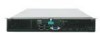
Installing a Compute Module into the Chassis, Removing or Installing the Top Cover - compute module manual
 |
UPC - 735858209250
View all Intel MFS5520VI manuals
Add to My Manuals
Save this manual to your list of manuals |
Page 28 highlights
4. Rotate the two lever handles outward and pull the compute module from the chassis slot. 5. Place either a filler or another compute module into the bay within one minute. This step is required to maintain proper airflow patterns throughout the chassis and to ensure proper chassis cooling. Installing a Compute Module into the Chassis To install a compute module into the chassis, follow these steps: 1. Observe the safety and ESD information at the beginning of this manual and in the appendices. 2. If you have not done so already, install any necessary options, such as processors, memory, hard drives and expansion cards in the compute module. Note: The top cover is a required component of the compute module; do not attempt to insert a compute module into a chassis without a top cover installed. 3. Make sure the retention levers on the compute module are in the open position. 4. Insert the compute module into an open slot in the chassis and slide it in until it stops. 5. Close the retention lever handles on the front of the compute module. Removing or Installing the Top Cover Removing the Top Cover To remove the top cover, follow these steps: 1. Observe the safety and ESD information at the beginning of this manual and in the appendices. 2. If the compute module is installed in a chassis, remove it. For instructions, see "Removing a Compute Module from the Chassis" on page 13. 3. Carefully lay the compute module down on a flat, non-conductive surface, with the cover side up. 14 Intel® Compute Module MFS5520VI User Guide
-
 1
1 -
2
-
3
-
4
-
5
-
6
-
7
-
8
-
9
-
10
-
11
-
12
-
13
-
14
-
15
-
16
-
17
-
18
-
19
-
20
-
21
-
22
-
 23
23 -
 24
24 -
 25
25 -
 26
26 -
 27
27 -
 28
28 -
 29
29 -
 30
30 -
 31
31 -
 32
32 -
 33
33 -
34
-
35
-
36
-
37
-
38
-
39
-
40
-
41
-
42
-
43
-
44
-
45
-
46
-
47
-
48
-
49
-
50
-
51
-
52
-
53
-
54
-
55
-
56
-
57
-
58
-
59
-
60
-
61
-
62
-
63
-
64
-
65
-
66
-
67
-
68
-
69
-
70
-
71
-
72
-
73
-
74
-
75
-
76
-
77
-
78
-
79
-
80
-
81
-
82
-
83
-
84
-
85
-
86
-
87
-
88
-
89
-
90
-
91
-
92
-
93
-
94
-
95
-
96
-
97
-
98
-
99
-
100
-
101
-
102
-
103
-
104
-
105
-
106
-
107
-
108
-
109
-
110
-
111
-
112
-
113
-
114
-
115
-
116
-
117
-
118
-
119
-
120
-
121
-
122
-
123
-
124
-
125
-
126
-
127
-
128
-
129
-
130
-
131
-
132
-
133
-
134
-
135
-
136
-
137
-
138
-
139
-
140
-
141
-
142
-
143
-
144
-
145
-
146
-
147
-
148
-
149
-
150
-
151
-
152
-
153
-
154
-
155
-
156
 |
 |
