Konica Minolta MS6000 MK II MS6000 MKII MSP3500 User Manual - Page 36
Parts of the Scanner, Projection Lamp Unit - support
 |
View all Konica Minolta MS6000 MK II manuals
Add to My Manuals
Save this manual to your list of manuals |
Page 36 highlights
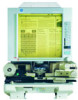
2-4 2. Parts of the Scanner Scanner Chapter 2 Screen: The image taken from the film is projected here for viewing. The frame on the Screen marks the data reading range. Control Panel: Many operations are controlled from the keys and indicators provided here. Image Rotation Knob: Used to turn the Prism Unit built into the Scanner, turning the image on the Screen. Projection Lens (Optional): Used to change the size and adjust the focus of the image on the Screen. Fiche Carrier 5 (Optional): Supports the viewing of microfiche. Projection Lamp Unit: Contains are Mirror and Lens which projects the film image onto the Screen. Connectors: Provides connection points for the various options (Roll Film Carrier and Controller). Power Cord Socket: Plug the power cord furnished with the Scanner into this socket. Power Switch: Used to turn power to the unit ON and OFF. Printer Connector: Connects the scanner to the printer through an interface cable. USB Connector (Optional): Connects the scanner to the Personal Computer through a USB cable.
-
 1
1 -
2
-
3
-
4
-
5
-
6
-
7
-
8
-
9
-
10
-
11
-
12
-
13
-
14
-
15
-
16
-
17
-
18
-
19
-
20
-
21
-
22
-
23
-
24
-
25
-
26
-
27
-
28
-
29
-
30
-
 31
31 -
 32
32 -
 33
33 -
 34
34 -
 35
35 -
 36
36 -
 37
37 -
 38
38 -
 39
39 -
 40
40 -
 41
41 -
42
-
43
-
44
-
45
-
46
-
47
-
48
-
49
-
50
-
51
-
52
-
53
-
54
-
55
-
56
-
57
-
58
-
59
-
60
-
61
-
62
-
63
-
64
-
65
-
66
-
67
-
68
-
69
-
70
-
71
-
72
-
73
-
74
-
75
-
76
-
77
-
78
-
79
-
80
-
81
-
82
-
83
-
84
-
85
-
86
-
87
-
88
-
89
-
90
-
91
-
92
-
93
-
94
-
95
-
96
-
97
-
98
-
99
-
100
-
101
-
102
-
103
-
104
-
105
-
106
-
107
-
108
-
109
-
110
-
111
-
112
-
113
-
114
-
115
-
116
-
117
-
118
-
119
-
120
-
121
-
122
-
123
-
124
-
125
-
126
-
127
-
128
-
129
-
130
-
131
-
132
-
133
-
134
-
135
-
136
 |
 |
