Konica Minolta magicolor 1600W Service Manual - Page 26
Composition of the service manual - error
 |
View all Konica Minolta magicolor 1600W manuals
Add to My Manuals
Save this manual to your list of manuals |
Page 26 highlights
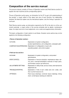
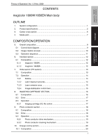
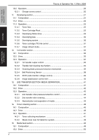
Composition of the service manual This service manual consists of Theory of Operation section and Field Service section to explain the main machine and its corresponding options. Theory of Operation section gives, as information for the CE to get a full understanding of the product, a rough outline of the object and role of each function, the relationship between the electrical system and the mechanical system, and the timing of operation of each part. Field Service section gives, as information required by the CE at the site (or at the customer's premise), a rough outline of the service schedule and its details, maintenance steps, the object and role of each adjustment, error codes and supplementary information. The basic configuration of each section is as follows. However some options may not be applied to the following configuration. OUTLINE: Explanation of system configuration, product specifications, unit configuration, and paper path COMPOSITION/OPERATION: Explanation of configuration of each unit, operating system, and control system OUTLINE: MAINTENANCE: ADJUSTMENT/SETTING: TROUBLESHOOTING: APPENDIX: Explanation of system configuration, and product specifications Explanation of service schedule, maintenance steps, service tools, removal/reinstallation methods of major parts, and firmware version up method etc. Explanation of utility mode, service mode, and mechanical adjustment etc. Explanation of lists of jam codes and error codes, and their countermeasures etc. Parts layout drawings, connector layout drawings, timing chart, overall layout drawing are attached. C-1
-
 1
1 -
2
-
3
-
4
-
5
-
6
-
7
-
8
-
9
-
10
-
11
-
12
-
13
-
14
-
15
-
16
-
17
-
18
-
19
-
20
-
 21
21 -
 22
22 -
 23
23 -
 24
24 -
 25
25 -
 26
26 -
 27
27 -
 28
28 -
 29
29 -
 30
30 -
 31
31 -
32
-
33
-
34
-
35
-
36
-
37
-
38
-
39
-
40
-
41
-
42
-
43
-
44
-
45
-
46
-
47
-
48
-
49
-
50
-
51
-
52
-
53
-
54
-
55
-
56
-
57
-
58
-
59
-
60
-
61
-
62
-
63
-
64
-
65
-
66
-
67
-
68
-
69
-
70
-
71
-
72
-
73
-
74
-
75
-
76
-
77
-
78
-
79
-
80
-
81
-
82
-
83
-
84
-
85
-
86
-
87
-
88
-
89
-
90
-
91
-
92
-
93
-
94
-
95
-
96
-
97
-
98
-
99
-
100
-
101
-
102
-
103
-
104
-
105
-
106
-
107
-
108
-
109
-
110
-
111
-
112
-
113
-
114
-
115
-
116
-
117
-
118
-
119
-
120
-
121
-
122
-
123
-
124
-
125
-
126
-
127
-
128
 |
 |