Konica Minolta magicolor 1600W Service Manual - Page 95
Transfer belt surface correction control - change toner
 |
View all Konica Minolta magicolor 1600W manuals
Add to My Manuals
Save this manual to your list of manuals |
Page 95 highlights
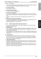
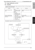
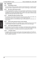
magicolor 1600W magicolor 1650EN 18. Image stabilization control Theory of Operation Ver. 1.0 Nov. 2008 18.2 Operation 18.2.1 Leak detection control • For the clearance between the photo conductor and developing roller, an optimum developing bias voltage is established that does not result in a leak image or uneven density. 18.2.2 IDC sensor LED intensity control • The following adjustment is made to correct any changes in characteristics occurring due to change with time and contamination of the IDC sensor (IDC): the intensity of the LED is adjusted for the surface of the transfer belt on which no toner sticks, so that the output value of the IDC sensor (IDC) becomes constant. 18.2.3 Transfer belt surface correction control • The reflectance of the Image transfer belt is measured using the ADIC sensor (IDC). One measurement is taken for one complete turn of the Image transfer belt. • The measured value is corrected during the laser intensity adjustment control and γ correction control. 18.2.4 Control of the maximum amount of toner sticking • The developing bias setting value is adjusted to keep constant the amount of toner sticking to the surface of the photo conductor with reference to the 100% solid image. 18.2.5 Laser intensity adjustment control • Characteristics of the photo conductor, developing, and charging change as affected by changes with time and in environment. The intensity of the laser light is adjusted so that fine lines and gradations of a predetermined level are reproduced at all times. 18.2.6 γ correction control • A gradation pattern is produced on the surface of the Image transfer belt. The IDC sensor (IDC) measures the density of the pattern and sends the measured result to the controller for gradation adjustment. COMPOSITION/ OPERATION 68
-
 1
1 -
2
-
3
-
4
-
5
-
6
-
7
-
8
-
9
-
10
-
11
-
12
-
13
-
14
-
15
-
16
-
17
-
18
-
19
-
20
-
21
-
22
-
23
-
24
-
25
-
26
-
27
-
28
-
29
-
30
-
31
-
32
-
33
-
34
-
35
-
36
-
37
-
38
-
39
-
40
-
41
-
42
-
43
-
44
-
45
-
46
-
47
-
48
-
49
-
50
-
51
-
52
-
53
-
54
-
55
-
56
-
57
-
58
-
59
-
60
-
61
-
62
-
63
-
64
-
65
-
66
-
67
-
68
-
69
-
70
-
71
-
72
-
73
-
74
-
75
-
76
-
77
-
78
-
79
-
80
-
81
-
82
-
83
-
84
-
85
-
86
-
87
-
88
-
89
-
 90
90 -
 91
91 -
 92
92 -
 93
93 -
 94
94 -
 95
95 -
 96
96 -
 97
97 -
 98
98 -
 99
99 -
 100
100 -
101
-
102
-
103
-
104
-
105
-
106
-
107
-
108
-
109
-
110
-
111
-
112
-
113
-
114
-
115
-
116
-
117
-
118
-
119
-
120
-
121
-
122
-
123
-
124
-
125
-
126
-
127
-
128
 |
 |