Konica Minolta magicolor 1600W Service Manual - Page 30

Theory of Operation

Page 30 highlights

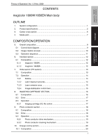
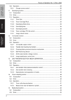
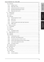
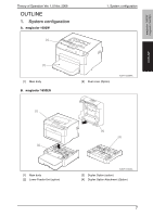
magicolor 1600W magicolor 1650EN OUTLINE COMPOSITION/ OPERATION Theory of Operation Ver. 1.0 Nov. 2008 CONTENTS magicolor 1600W/1650EN Main body OUTLINE 1. System configuration 1 2. Product specifications 2 3. Center cross section 6 4. Media path ...7 COMPOSITION/OPERATION 5. Overall composition 9 5.1 Control block diagram 9 5.2 Image creation process 10 5.3 Operation sequence 11 6. Interface section ...12 6.1 Composition...12 6.1.1 magicolor 1600W 12 6.1.2 magicolor 1650EN 12 7. Write section (PH section 13 7.1 Composition...13 7.2 Operation ...14 7.2.1 Outline...14 7.2.2 Laser exposure process 14 7.2.3 Laser emission area 15 7.2.4 Image stabilization control item 15 8. IMAGEING CARTRIDGE SECTION 16 8.1 Composition...16 8.2 Drive ...17 8.3 Operation ...17 8.3.1 Imaging cartridge (IC) life control 17 9. Photo conductor section 18 9.1 Composition...18 9.2 Drive ...18 9.3 Operation ...19 9.3.1 Photo conductor drive mechanism 19 9.3.2 Photo conductor cleaning mechanism 19 10. Charge corona section 20 10.1 Composition...20 i

  • 1
  • 2
  • 3
  • 4
  • 5
  • 6
  • 7
  • 8
  • 9
  • 10
  • 11
  • 12
  • 13
  • 14
  • 15
  • 16
  • 17
  • 18
  • 19
  • 20
  • 21
  • 22
  • 23
  • 24
  • 25
  • 26
  • 27
  • 28
  • 29
  • 30
  • 31
  • 32
  • 33
  • 34
  • 35
  • 36
  • 37
  • 38
  • 39
  • 40
  • 41
  • 42
  • 43
  • 44
  • 45
  • 46
  • 47
  • 48
  • 49
  • 50
  • 51
  • 52
  • 53
  • 54
  • 55
  • 56
  • 57
  • 58
  • 59
  • 60
  • 61
  • 62
  • 63
  • 64
  • 65
  • 66
  • 67
  • 68
  • 69
  • 70
  • 71
  • 72
  • 73
  • 74
  • 75
  • 76
  • 77
  • 78
  • 79
  • 80
  • 81
  • 82
  • 83
  • 84
  • 85
  • 86
  • 87
  • 88
  • 89
  • 90
  • 91
  • 92
  • 93
  • 94
  • 95
  • 96
  • 97
  • 98
  • 99
  • 100
  • 101
  • 102
  • 103
  • 104
  • 105
  • 106
  • 107
  • 108
  • 109
  • 110
  • 111
  • 112
  • 113
  • 114
  • 115
  • 116
  • 117
  • 118
  • 119
  • 120
  • 121
  • 122
  • 123
  • 124
  • 125
  • 126
  • 127
  • 128

magicolor 1600W
magicolor 1650EN
OUTLINE
COMPOSITION/
OPERATION
Theory of Operation
V
er. 1.0
N
ov. 200
8
i
CO
N
TE
N
TS
magicolor 1600W/1650E
N
Main body
OUTLI
N
E
1.
System configuration
...............................................................................................
1
2.
Product specifications
.............................................................................................
2
3.
Center cross section
...............................................................................................
6
4.
Media path
..............................................................................................................
7
COMPOSITIO
N
/OPERATIO
N
5.
Overall composition
.................................................................................................
9
5.1
Control block diagram
...........................................................................................
9
5.2
Image creation process
......................................................................................
10
5.3
Operation sequence
...........................................................................................
11
6.
Interface section
....................................................................................................
12
6.1
Composition
........................................................................................................
12
6.1.1
magicolor 1600W
........................................................................................
12
6.1.2
magicolor 1650E
N
......................................................................................
12
7.
Write section (PH section)
.....................................................................................
13
7.1
Composition
........................................................................................................
13
7.2
Operation
............................................................................................................
14
7.2.1
Outline
.........................................................................................................
14
7.2.2
Laser exposure process
..............................................................................
14
7.2.3
Laser emission area
....................................................................................
15
7.2.4
Image stabilization control item
...................................................................
15
8
.
IMAGEI
N
G CARTRIDGE SECTIO
N
.....................................................................
16
8
.1
Composition
........................................................................................................
16
8
.2
Drive
...................................................................................................................
17
8
.3
Operation
............................................................................................................
17
8
.3.1
Imaging cartridge (IC) life control
................................................................
17
9.
Photo conductor section
........................................................................................
1
8
9.1
Composition
........................................................................................................
1
8
9.2
Drive
...................................................................................................................
1
8
9.3
Operation
............................................................................................................
19
9.3.1
Photo conductor drive mechanism
..............................................................
19
9.3.2
Photo conductor cleaning mechanism
........................................................
19
10.
Charge corona section
..........................................................................................
20
10.1
Composition
........................................................................................................
20