LG 32LX4DC User Manual - Page 19
HDSTB Setup
 |
View all LG 32LX4DC manuals
Add to My Manuals
Save this manual to your list of manuals |
Page 19 highlights
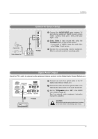
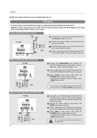
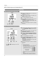
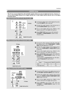
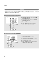
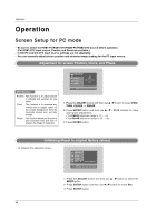
Installation HDSTB Setup - This TV can receive Digital Over-the-air/Cable signals without an external digital set-top box. However, if you do receive Digital signals from a digital set-top box or other digital external device, refer to the figure as shown below. When connecting with a D-sub 15 pin cable AC IN PC AUDIO INPUT2 PC INPUT2 DIGITAL AUDIO (OPTICAL) SPEAKER OUT RS-232C INPUT (CONTROL/SERVICE) OUTPUT PC AUDIO INPUT1 PC INPUT1 COMPONENT1/DVI INPUT TV Back 2 1 Digital Set-top Box (R) AUDIO (L) RGB-DTV OUTPUT When connecting with a Component cable TV Back DVI INPUT (PC/DTV INPUT) S-VIDEO R AUDIO L/MONO VIDEO VIDEO1 COMPONENT1 R L AUDIO INPUT VIDEO INPUT Antenna 2 1 1 Connect the RGB output of the digital set-top box to the PC INPUT1 jack on the set. 2 Connect the audio outputs of the set-top box to the PC AUDIO INPUT1 jack on the set. 3 Turn on the digital set-top box. (Refer to the owner's manual for the digital set-top box.) 4 Select RGB1-DTV input source with using the TV/VIDEO or COMP/RGB/DVI button on the remote control. 1 Connect the video outputs (Y, PB, PR) of the digital set-top box to the COMPONENT1 VIDEO INPUT (Y, PB, PR) jacks on the set. 2 Connect the audio outputs of the digital set-top box to the COMPONENT1 AUDIO INPUT jacks on the set. 3 Turn on the digital set-top box. (Refer to the owner's manual for the digital set-top box.) 4 Select Component 1 input source with using the TV/VIDEO or COMP/RGB/DVI button on the remote control. - If connected to COMPONENT2 input (TV side) , select Component 2 input source. (R) AUDIO (L) B R Digital Set-top Box When connecting with a DVI cable DIGITAL AUDIO (OPTICAL) DVI INPUT (PC/DTV INPUT) S-VIDEO R AUDIO L/MONO VIDEO OUTPUT VIDEO1 COMPONENT1 COMPONENT1/DVI INPUT R L AUDIO INPUT VIDEO INPUT Antenna 2 1 TV Back DIGITAL AUDIO OPTICAL DVI-DTV OUTPUT Digital Set-top Box Signal Component1/2 RGB-DTV, DVI-DTV 480i Yes No 480p/720p/1080i Yes Yes 1 Connect the DVI output of the digital set-top box to the DVI INPUT (PC/DTV INPUT) jack on the set. 2 Connect the digital audio outputs of the set-top box to the DIGITAL AUDIO COMPONENT1/DVI INPUT jack on the set. 3 Turn on the digital set-top box. (Refer to the owner's manual for the digital set-top box.) 4 Select DVI-DTV input source with using the TV/VIDEO or COMP/RGB/DVI button on the remote control. 19
-
 1
1 -
2
-
3
-
4
-
5
-
6
-
7
-
8
-
9
-
10
-
11
-
12
-
13
-
 14
14 -
 15
15 -
 16
16 -
 17
17 -
 18
18 -
 19
19 -
 20
20 -
 21
21 -
 22
22 -
 23
23 -
 24
24 -
25
-
26
-
27
-
28
-
29
-
30
-
31
-
32
-
33
-
34
-
35
-
36
-
37
-
38
-
39
-
40
-
41
-
42
-
43
-
44
-
45
-
46
-
47
-
48
-
49
-
50
-
51
-
52
-
53
-
54
-
55
-
56
-
57
-
58
-
59
-
60
 |
 |
