LG HMC030KD1 Service Manual
LG HMC030KD1 Manual
 |
View all LG HMC030KD1 manuals
Add to My Manuals
Save this manual to your list of manuals |
LG HMC030KD1 manual content summary:
- LG HMC030KD1 | Service Manual - Page 1
MODEL EIRIC0301W1 H030KD1 SERVICING THEUNIT, READ THE "SAFETY PRECAUTIONS" IN THIS MANUAL -ONLY FOR AUTHORIZED SERVICE PERSONNEL. nternatlonai iomrort r uc s - LG HMC030KD1 | Service Manual - Page 2
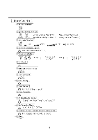
Specifications Refrigeration Cycle Diagram Pipe Length and tha Flevation 10 iring uiagram Operation Details Display Function noels Function ns a a ion Operation Disassembly of the parts (Indoor Unit) -way valve 43 Cycle Troubleshooting Guide Electronic Parts Troubleshooting Guide - LG HMC030KD1 | Service Manual - Page 3
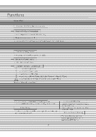
Indoor Unit Operation Sensing the Room Temperature • Room temperature Room temperature control • Maintains the ron -. le-. . 1 - . 0E- - , Starting Current Control • Indoor fan is delayed for 5 seconds at the starting. Time Delay Safety Control • Restarting s' "e o approx. 3 minutes. . ernp - LG HMC030KD1 | Service Manual - Page 4
Remote Controller Operation ON/OFF 0 Operation Mode Selection *A() *A0O (Cooling (Heating model only) model only) Cooling Operation Mode.( * ) Auto Operation Mode.( A ) Healthy Dehumidification Operation Mode.( 0 ) Heating Operation Mode.( ) Fan Speed Selection (Low) (Med) (High) Q4 ( - LG HMC030KD1 | Service Manual - Page 5
- LG HMC030KD1 | Service Manual - Page 6
- LG HMC030KD1 | Service Manual - Page 7
mensions Tubing hole cover ti Installation plate • Tubingiiole cover • menslon m(inch) mm inch 205(8.1) 7 - LG HMC030KD1 | Service Manual - Page 8
2) Outdoor Unit L./ I L6 nim W H D L3 L5 L7 L8 L9 L11 MODEL mm(in ch) mm(in ch mm(in ch) m(in ch) mm(in ch1 mmtm C mm(in ch mm(in ch) mm(in ch) mm(in ch) mm(in ch) mm(in ch) mm(in ch) Gas side 3-way valve Liquid side 3-way valve 30K SERIES 870(34.3) 800 31 5 320(12.6) 340(13.4) 2 1 25(1.0 546( - LG HMC030KD1 | Service Manual - Page 9
e ngera ion c e uiagra (1) Cooling Only Models HEAT EXCHANGER (011017N CAPILLARY TUBE FltA I EXCHANGER (CONDENSER) ne Cooling & Heating Mode INDOOR UNIT vaparator Line 3-WAY VALVE HEAT EXCHANGER (EVAPORATOR) OUTDOOR UNIT CHECK VALVE (Heating Model only) 000 0000 `CAPILLARY TUBE HEAT EXCHANGER ( - LG HMC030KD1 | Service Manual - Page 10
/h) 30k (50Hz, 60Hz) Pipe Size GAS LIQUID 5/8" 3/8" Standard Length m(ft) 7.5(25) Max. Elevation © m(ft) 15(50) Max. Length 0 m(ft) 30(100) Additional Refrigerant g/m(oz/ft) 30(0.32) Outdoor unit Indoor unit Outdoor unit Oil trap Indoor unit .1 In case more than 5m (16.4ft) * Capicity is - LG HMC030KD1 | Service Manual - Page 11
- LG HMC030KD1 | Service Manual - Page 12
- LG HMC030KD1 | Service Manual - Page 13
. when operating initially, to prevent noises occurred by the vertical louver and-vond. relmrsing vabzeisilelayed for2-m-trwrtes-trrpreve-nt-the-refrigerant-gasincalm=il noise when the. heating:operation is_OFEurvecitaied to the other operation mode white conipwshuri.suff While prc of I b Itch - LG HMC030KD1 | Service Manual - Page 14
_ Auto Operation (Electronic control mode) • The operation procedure is shown bel Pre tnp Button, pera ion mode Indoor fan speed cesr• t re are decided automatically by the unit electronic control temgerature era on Mode urilial erode is decided, Id below 70°F 70°F 76°F eat n e is - LG HMC030KD1 | Service Manual - Page 15
Auto Operation for Dehumidification(only Heati --The-Sethng-temperature will be-same that of Compressor ON temperatureSetting temperature 2°F - Compressor OFF temperature; Setting ternpailure=1--T ■ Auto Operation for lloating(only Heating Model -eompressor attemperature;-Settingtemperature- z. - LG HMC030KD1 | Service Manual - Page 16
• When the dehumidifi detected and the setting temp is automatically set acrording to the intake air temperature 26°C-51- c i 0- 25°C 24°C 5 Intake Intake Air Temp - LG HMC030KD1 | Service Manual - Page 17
Heating Operation Mode(only Heating Model The unit will operate-according-to-the setting conditions by the remote-controller. The-operation-diagram is shown bciow. NTAKE AIR TEMP: _SETTING TEMP. +6°F (Compressor OFF) TEMP. (Compressor ON; minimum MrlITIUM minimum NDOOR FAN SPE OMPRESSOR - LG HMC030KD1 | Service Manual - Page 18
7 ftrinlIna nr Hee'no 1111nria with Gloop-Mode-Auto-Control • When selecting the Cooling( ) or the Heating( combined with the Sleep Mode Auto Control( the operation diagram is as-following. -0-Cooling-Mode-with the Sleep Mode • The setting temperature will be autom ally raised by 2°F 30 minutes - LG HMC030KD1 | Service Manual - Page 19
8. Forced Operation To operate the appliance by force in case that the remote controller is lost, the forced operation button is on the main unit of the appliance to operate the appliance in the standard conditions. • Press the forced operation button, the forced operation is carried out. • Press - LG HMC030KD1 | Service Manual - Page 20
Display Function Signal Receptor Receives the signals from the remote control.(Signal receiving sound: two short beeps or one long beep.) Operation Indication Lamps On/Off : Lights up during the system operation. 0 Timer or Sleep Mode : Lights up during Timer operation or Sleep mode. o Defrost - LG HMC030KD1 | Service Manual - Page 21
step by step. 1. Installation of Indoor, Outdoor unit Installation Parts Provided 1. Type "A" screw -02. Installation Plate 3. Type 'B' as non serviceable installation. 2) Piping length and elevation Capacity (Btuiti) 30k Sandard Pipe Size l_ten F EleMvaaxtiOn leInlgIxil Refrigerant GAS LIQUID - LG HMC030KD1 | Service Manual - Page 22
WALL Indoor Outdoor E E C to 2. Measure the wall and mark the centerline. It is also important to use caution concerning the location of the installation plate-routing of the wiring to power outlets is through the walls typically. Drilling the hole through the wall for piping connections must be - LG HMC030KD1 | Service Manual - Page 23
2. Flaring Work and Connection of Piping 1) Flaring work Main cause for gas leakage is due to defect in flaring work. Carry out correct flaring work in the following procedure. 1. Cut the pipes and the cable. • Use the piping kit accessory or the pipes purchased locally. • Measure the distance - LG HMC030KD1 | Service Manual - Page 24
2) Connection of piping-Indoor 1. Remove the 2 screws of right side panel. Right side panel CAUTION When install, make sure that the remaining parts must be removed clearly so as not to damage the piping and drain hose, especially power cord and connecting cable. • a • ••• 2. Remove the front - LG HMC030KD1 | Service Manual - Page 25
(Btu/h) 30K Pipe Size[Torque] Suction Evaporator 5/8"[6.6kg.nn] 3i8'[4.2kg.rn] • When extending the drain hose at the indoor unit, install the drain pipe. 0 Drain pipe Indoor unit ,,,,---Three upper ks hInosotallation - , plate Three lower hooks - 25 - Indoor unit drain hose Adhesive - LG HMC030KD1 | Service Manual - Page 26
- tOttrapillidnsulaliattmaterlablmand the connecting Fight rearpiping portion. • Overlap the cenneetton-otoe-tnsuletton-material an • door unit pipe-insulation material. Bind them together with vinyl tape so that there is no gap. 1. Route the Indoor tubing and the drain hose to the required - LG HMC030KD1 | Service Manual - Page 27
the drain pipe. Drain hose 0 Indoor unit drain hose Adhesive Vinyl tape (narrow) Indoor unit _....„--Three upper (,LI', hooks Installation -- plate Three lower hooks 7. Wrap the insulation material around the connecting portion. ■ Overlap the connection pipe heat insulation and the indoor - LG HMC030KD1 | Service Manual - Page 28
with cloth tape over the range within which they fit into the rear piping housing section. ❑rain hose Pipe Vinyl tape(narrow) 9. Reinstall the parts to the original position. ■ Refix the lower panel to the original position. 4 Wrap with vinyl tape(wide) Lower panel • Connect display conductor - LG HMC030KD1 | Service Manual - Page 29
3) Connection of the drain hose • The drain hose can be connected at two different positions. Use the most convenient position and, if necessary, exchange the position of the drain pan, rubber cap and the drain hose. O Drain pan *9 Rubber cap O Drain hose O Exchange if necessary • Remove the drain - LG HMC030KD1 | Service Manual - Page 30
3. Connecting the cable between indoor unit and outdoor unit 1) Connect the cable to the indoor unit by connecting the wires to the terminals on the control board individually according to the outdoor unit connection. (Ensure that the color of the wires of the outdoor unit and the terminal No. are - LG HMC030KD1 | Service Manual - Page 31
5nun nr I -- IIIM.71 an /kV After the onfirmation of the above conditions, prepare ng as follows: j=Neviwfail4ohave-anindivi • • of wiring, be guided by the ceLuit diagram-posted-orrtheinside-of-control-cover. 2)--The-serew-which-fasten-the-wiring vibrations-te-whieh-the-unifWsub -sure-that - LG HMC030KD1 | Service Manual - Page 32
1) Checking the drainage 1. Remove the right side panel. Hight side panel 4. To check the drainage. • Pour a glass of water on the drain pan. • Ensure the water flows through the drain hose of the indoor unit without any leakage and goes out the drain exit 2. Remove the lower panel by the arrow. I - LG HMC030KD1 | Service Manual - Page 33
be routed above the ground. Secure the drain hose appropriately. 2. In cases where the outdoor unit is installed below the indoor unit perform the following. • Tape the piping, drain hose and connecting cable from down 30K Trap is required to prevent water from entering into electrical parts. - 33 - - LG HMC030KD1 | Service Manual - Page 34
■ Moisture in the refrigerant circuit may freeze and block capillary tubing. ■ Water may lead to corrosion of parts in the refrig- eration Connect the manifold valve(with pressure gauges) and dry nitrogen gas cylinder to this service port with charge hoses. A CAUTION Be sure to use a manifold valve - LG HMC030KD1 | Service Manual - Page 35
15 min or more When the desired vacuum is h dclose th "Lo" knob of the manifold valvc a vacuum pump. ling the j • With a service valve wrench, turolhe_valve_ste of liquid side valve counter-clockwise to full open the-valve- IN Turn thesalweztwatt gas_side_valve counterclockwise to fully open the - LG HMC030KD1 | Service Manual - Page 36
o1Ornm) tightly and horizontally on a concrete or rigid mount. ■ When installing on the wall, roof or rooftop, anchor the mounting base securely with or the refrigerant circuit is serviced. Pump Down means collecting all refrigerant in the outdoor unit without loss in refrigerant gas. CAUTION - LG HMC030KD1 | Service Manual - Page 37
Operation (1) Name and Function-Remote Control (Cooling Models) Remote Controller Signal transmitter. Transmits the signals to the room air conditioner. Signal transmitter ins •7:-• *i!,A„oiniri*r+ . mtighlli41 IMBITIME OM TIME NIAK.000 ratOBB 0;7 0 11,111 ON- -OFF • 4D: SET-G -CANCEL 121 *AO - LG HMC030KD1 | Service Manual - Page 38
(2) Name and Function-Remote Control (Heat Pump Models) Remote Controller Signal transmitter. Transmits the signals to the room air conditioner. Signal transmitter s ,ltischT -7,-B tt*A 4 -)+ JET E®2,mI,NTTIIME ®TIME VA:B-BB Ell; Ill c-4 Ocb \2.) ON-ci -OFF 0 0 SET- -CANGEL *AO* f =_1r-'a- ' - LG HMC030KD1 | Service Manual - Page 39
Disassembly of the parts (Indoor unit) Warning : Disconnect the unit from power supply before making any checks. Be sure the power switch is set to "OFF". 1. To remove the - LG HMC030KD1 | Service Manual - Page 40
0 Remove the grille from the chassis. • Remove the 4 securing screws.(30K, 32K) • Remove the 5 securing screws.(36K, 38K) • To remove the Grille, pull the lower le₹t and right side of the grille toward you (slightly tilted) and lift it straight upward. 30K 2. To remove the sensor, housing connector - LG HMC030KD1 | Service Manual - Page 41
3. To remove the Control Box. • Remove the 5 securing screws. • Pull the control box out from the chassis carefully. 4. To remove the Discharge Grille. • Remove the 3 securing screw. • Pressing the right side of the discharge grille downward slightly, unhook the discharge grille. • Pull the - LG HMC030KD1 | Service Manual - Page 42
6. To remove the Fan motor • Loosen the screw securing the cross-flow fan to the fan motor (do not remove). II 00- • Loosen the screw securing the mount motor. Fan motor Arlo Screw • Separate the fan motor from the cross-flow fan. • Take care not to drop the motor Screw --Mount motor Fan - LG HMC030KD1 | Service Manual - Page 43
unit for 10 to 15 minutes. (3) Stop operation and wait for 3 minutes, then connect the charge set to the service port of the Gas side valve. - Connect the charge hose to the service port. (4) Air purging of the charge hose. - Open the low-pressure valve on the charge set slightly to air - LG HMC030KD1 | Service Manual - Page 44
Re-installation) refrigerant until the gauge indicates 3 to 5 kg/cm2g. (6) Disconnect the charge set and the gas cylinder, and set the Liquid side and Gas side valves to the open position. - Be sure to use a hexagonal wrench to operate the valve stems. (7) Mount the valve stem nuts and the service - LG HMC030KD1 | Service Manual - Page 45
on the charge set closed. Connect the charge hose to the service port. (3) Open the valve (Lo side) on the charge set and discharge the refrigerant until the gauge indicates 0 kg/cm2G. - If there is no air in the refrigerant cycle (the pressure when the air conditioner is not running is higher - LG HMC030KD1 | Service Manual - Page 46
2. Evacuation (All amount of refrigerant leaked) Indoor uni Liquid side 3-Way valet" Open ❑utdoor unit Gas side 3-Way valve Open Vacuum pump Wj L OPEN CLOSE • Procedure (1) Connect the vacuum pump - LG HMC030KD1 | Service Manual - Page 47
from the gas side, absolutely do not attempt to charge with larger amounts of liquid refrigerant while operating the air conditioner. (4) Immediately disconnect the charge hose from the 3-way valve's service port. - Stopping partway will allow the gas to be discharged. - If the system has been - LG HMC030KD1 | Service Manual - Page 48
the normal value) Higher Temperature (Compared with the normal valve) High Normal Cause' of Trouble Defective compressor r-wespe.c.ive-AMAHIffit-Afrefrigerant Lower Hiy ur Insufficient amount of refrigerant (Leakage) Clogging Dcsc►'iptinn is low. High pressnr-P, FIAAR-Fint-cp-tinkly- rise at - LG HMC030KD1 | Service Manual - Page 49
of Misers-No. 2, n oor unit (DC +4.5V over)-and Soldering condition, No-5-(Outdoor=unit) -•-Replace IC0l D (Outdoor unit) -.-Replace IC02D Otrtdoor-urrit)- ( n our unit)- -Replaeefaulty parts- - 49 - - LG HMC030KD1 | Service Manual - Page 50
-Gentroired by the remote-Grantroller. When operated in the, Sleeping,Modethe=wind speed is w speed by force.) ause nv the remote controner Cause&brether-parts-exeept-the-remdte-eantroller- 2) When the mark( Is &played in LCD screen. rp,plarR FY Check contact ot GN-DISP connectur. - When-the - LG HMC030KD1 | Service Manual - Page 51
is disconnected or-net(About 101i)I at 25CC). or.(Outultorumi)_ • When-the-pewer(Abeut AC220V/240Wie-applied to the connecting wire terminal support transferred to compressor, PWB Asey4s4lormal. • Check the circuit related to the relay Cneck point Between Micotti(Nu.15) arid GND Between lielay - LG HMC030KD1 | Service Manual - Page 52
tolUIIdMITA I:1 T.V-AW.1•14•7.1 laTaTa I 91:1.01:1IIL:10DLIIIA-15•17/ I LOAI.01'A' II Al .AUAOJI .ZA/151:.ALL:CIAJ Li11mOmoviris i:210.t .e.o ill• • ▪ .T•11f lii r.1Ft•T• rilfiTT-t•T• INIEellil G•F&II Ca rr l.fell ray :All ISzitli F- Ts • 1 i :PUNIC 61 Si•I r, • •UI • • I • • • 1,1 - LG HMC030KD1 | Service Manual - Page 53
so) andC) of MICOM - Between (:), a Oland O of ICO1M - Between 6, O, and of IC01M If there are no problems after above checks • Confirm the assembly conditions that are catching and interfering parts in the rotation radial of the Vertical Louver 6. When Heating does not operate Turn ON Main Power - LG HMC030KD1 | Service Manual - Page 54
P rnnnery r nr IfTRKP an sensor( PITT11.-1 rs) • Check-the-related-circuit of R02H( , Micom( o. 3, 4). • Cheek-theindoor-room temperature-is-disemneetecFar-not ( 10M-2/at 25°C). cck the indmwrfIrwtemmiratireqs9lIszsfruwtRI9R not (about- 5KWat 25°C) Ie QCCdlIb ullurlrlflgb • Como Rela - LG HMC030KD1 | Service Manual - Page 55
JUL MO 0 III • • tt-14," JC II =1 I ••• - LG HMC030KD1 | Service Manual - Page 56
- LG HMC030KD1 | Service Manual - Page 57
- LG HMC030KD1 | Service Manual - Page 58
- LG HMC030KD1 | Service Manual - Page 59
(2) Heat Pump Series (Outdoor Unit) 5 7 7 z Vgi I HI MM 9 3 1 g 3 13 0 1 - 59 - - LG HMC030KD1 | Service Manual - Page 60
Exploded View and Replacement Parts List 1. Indoor Unit Min 4280 , •• 3141 3301 2390- Cpoit3) 4280 3531 ..14t 46811 13530 5421 • 59011- 4681 52390- 3531 3531 C1_523.1 5990 • 5215 46811- 5211 6871 6323 OCZ 4995 (26711 5230 13531 6871 Cf5230Z) -60- - LG HMC030KD1 | Service Manual - Page 61
- LG HMC030KD1 | Service Manual - Page 62
2. Outdoor Unit 43551 43721 37213- 37213- 43530 4961 4681 5901 61411 5220 OCZZEZZ 5211 ail i (263230 6871 43551 995 44791 • 5220 5220352203- 54160- 5211 6141 6600 54160- 6750 43041 0140- 50140 S - 62 - - LG HMC030KD1 | Service Manual - Page 63
- LG HMC030KD1 | Service Manual - Page 64
-
 1
1 -
 2
2 -
 3
3 -
 4
4 -
 5
5 -
 6
6 -
 7
7 -
8
-
9
-
10
-
11
-
12
-
13
-
14
-
15
-
16
-
17
-
18
-
19
-
20
-
21
-
22
-
23
-
24
-
25
-
26
-
27
-
28
-
29
-
30
-
31
-
32
-
33
-
34
-
35
-
36
-
37
-
38
-
39
-
40
-
41
-
42
-
43
-
44
-
45
-
46
-
47
-
48
-
49
-
50
-
51
-
52
-
53
-
54
-
55
-
56
-
57
-
58
-
59
-
60
-
61
-
62
-
63
-
64
 |
 |

MODEL
EIRIC0301W1
H030KD1
SERVICING
THEUNIT,
READ
THE
"SAFETY
PRECAUTIONS"
IN
THIS
MANUAL
-ONLY
FOR
AUTHORIZED
SERVICE
PERSONNEL.
nternatlonai
iomrort
r
uc
s