LG HMC030KD1 Service Manual - Page 25
Size[Torque]
 |
View all LG HMC030KD1 manuals
Add to My Manuals
Save this manual to your list of manuals |
Page 25 highlights
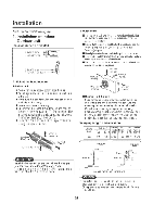
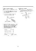
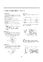
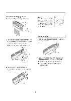
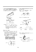
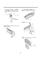
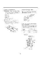
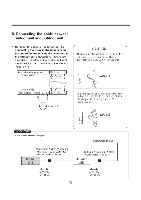
3. Tape the tubing, drain hose and the connecting cable. Be sure that the drain hose is located at the lowest side of the bundle. Locating at the upper side can cause drain pan to overflow inside the unit. 5. Connecting the pipings to the indoor unit and drain hose to drain pipe. • Align the center of the pipings and sufficiently tighten the flare nut by hand. -10\mt MAP Indoor unit tubing Flare nut Pipings • , • • Loop r Connecting (t, cable : Drain hose Gas side piping Liquid side piping NOTE: If the drain hose is routed inside the room, insulate the hose with an insulation material* so that dripping from "sweating"(condensation) will not damage furniture or floors. *Foamed polyethylene or equivalent is recommended. 4. Indoor unit installation • Hook the indoor unit onto the upper portion of the installation plate.(Engage the three hooks of the rear top and rear lower of the indoor unit with the upper edge and lower edge of the installation plate.) Ensure that the hooks are properly seated on the installation plate by moving it left and right installation plate Setting line • Tighten the flare nut with a wrench. Indoor unit tubing Connection pipe Flare nut Spanner (fixed) Torque wrench Capacity (Btu/h) 30K Pipe Size[Torque] Suction Evaporator 5/8"[6.6kg.nn] 3i8'[4.2kg.rn] • When extending the drain hose at the indoor unit, install the drain pipe. 0 Drain pipe Indoor unit ,,,,---Three upper ks hInosotallation - , plate Three lower hooks - 25 - Indoor unit drain hose Adhesive Vinyl tape(narrow)
-
 1
1 -
2
-
3
-
4
-
5
-
6
-
7
-
8
-
9
-
10
-
11
-
12
-
13
-
14
-
15
-
16
-
17
-
18
-
19
-
 20
20 -
 21
21 -
 22
22 -
 23
23 -
 24
24 -
 25
25 -
 26
26 -
 27
27 -
 28
28 -
 29
29 -
 30
30 -
31
-
32
-
33
-
34
-
35
-
36
-
37
-
38
-
39
-
40
-
41
-
42
-
43
-
44
-
45
-
46
-
47
-
48
-
49
-
50
-
51
-
52
-
53
-
54
-
55
-
56
-
57
-
58
-
59
-
60
-
61
-
62
-
63
-
64
 |
 |
