LG HMC030KD1 Service Manual - Page 30
Connecting, cable, between, indoor, outdoor
 |
View all LG HMC030KD1 manuals
Add to My Manuals
Save this manual to your list of manuals |
Page 30 highlights
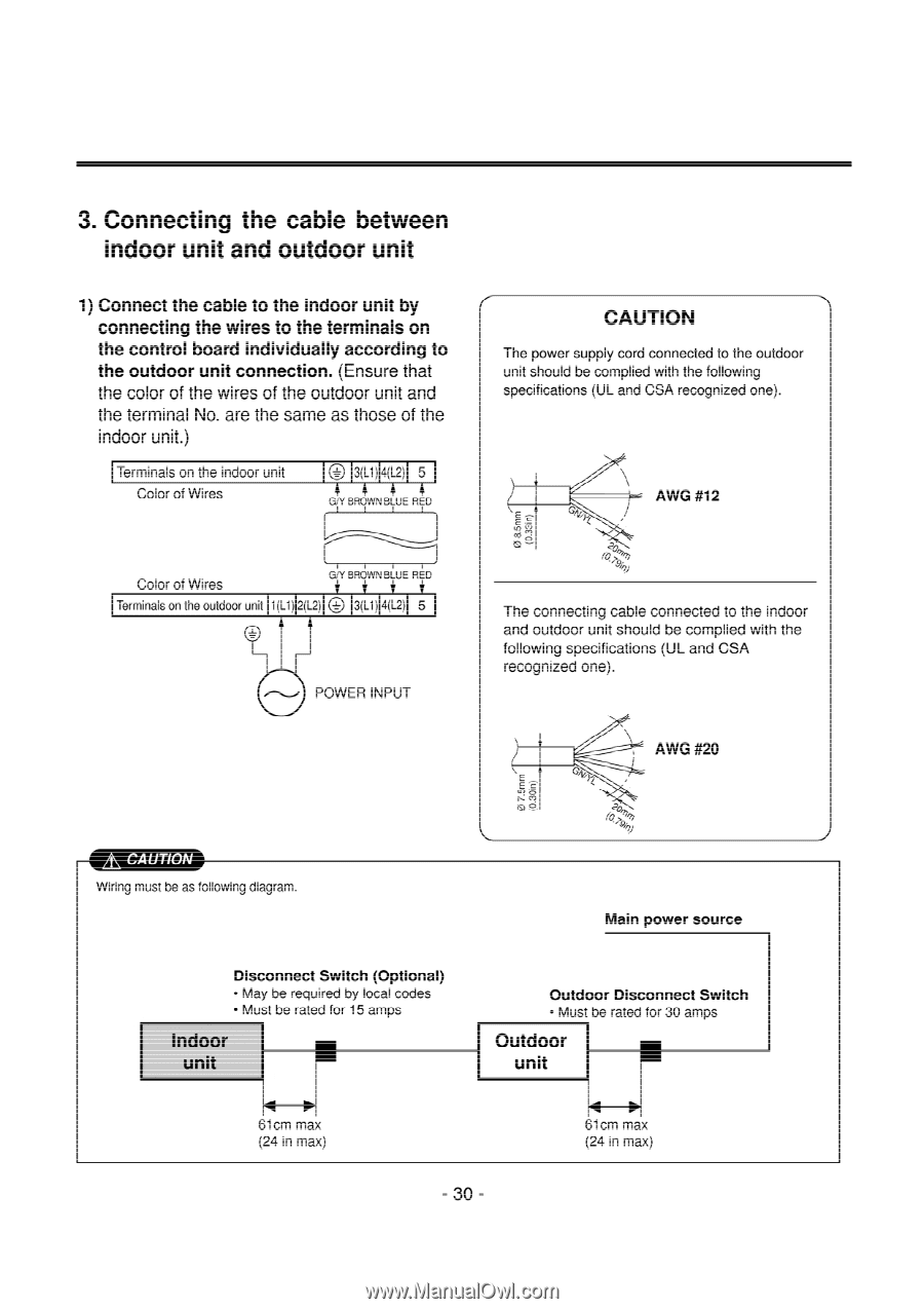
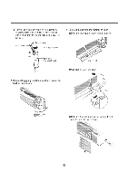
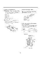
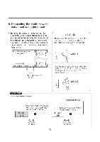
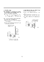
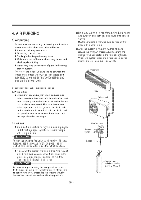
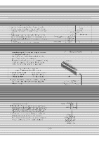
3. Connecting the cable between indoor unit and outdoor unit 1) Connect the cable to the indoor unit by connecting the wires to the terminals on the control board individually according to the outdoor unit connection. (Ensure that the color of the wires of the outdoor unit and the terminal No. are the same as those of the indoor unit.) Terminals on the indoor unit Color of Wires I® 3(L1) 4(L2) 5 4 4 4 4, GO' BROWN BLUE RED Color of Wires GiY BROWN BLUE RED Terminals on the outdoor unit 1(L1) 2(L2) 3(L1) 4(L2) 5 POWER INPUT CAUTION The power supply cord connected to the outdoor unit should be complied with the following specifications (UL and GSA recognized one). AWG #12 E E -E The connecting cable connected to the indoor and outdoor unit should be complied with the following specifications (UL and GSA recognized one). AWG #20 A\ CAUTION Wiring must be as following diagram. Main power source Disconnect Switch (Optional) • May be required by local codes • Must be rated for 15 amps . .7 Indoor unit 61cm max (24 in max) Outdoor Disconnect Switch • Must be rated for 30 amps 14_0. Outdoor unit 61cm max (24 in max) - 30 -
-
 1
1 -
2
-
3
-
4
-
5
-
6
-
7
-
8
-
9
-
10
-
11
-
12
-
13
-
14
-
15
-
16
-
17
-
18
-
19
-
20
-
21
-
22
-
23
-
24
-
 25
25 -
 26
26 -
 27
27 -
 28
28 -
 29
29 -
 30
30 -
 31
31 -
 32
32 -
 33
33 -
 34
34 -
 35
35 -
36
-
37
-
38
-
39
-
40
-
41
-
42
-
43
-
44
-
45
-
46
-
47
-
48
-
49
-
50
-
51
-
52
-
53
-
54
-
55
-
56
-
57
-
58
-
59
-
60
-
61
-
62
-
63
-
64
 |
 |