LG HMC030KD1 Service Manual - Page 31
After, follows
 |
View all LG HMC030KD1 manuals
Add to My Manuals
Save this manual to your list of manuals |
Page 31 highlights
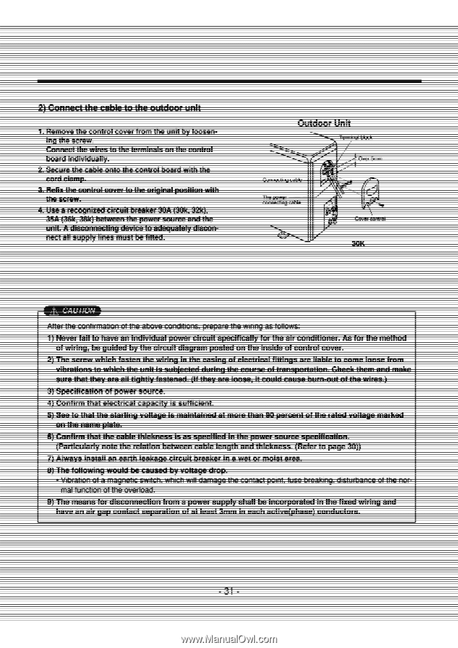
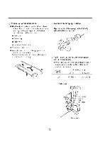
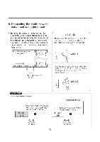
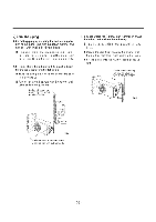
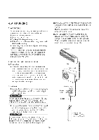
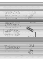
nneci o ice ouwoor un 1. Remove the cont over from the unit by loosening the screw. Connect the_wiresYLthe terminals on the control board indivaially ord CI the screw. i WI 4. Use a recognized circuit breaker 30A (30k, 32k), (36k, 38k) between Po unit. A disconnecting device to adequately discon- onnecting cable e poweo nnecting ca Terminal block Over 5nun nr I -- IIIM.71 an /kV After the onfirmation of the above conditions, prepare ng as follows: j=Neviwfail4ohave-anindivi • • of wiring, be guided by the ceLuit diagram-posted-orrtheinside-of-control-cover. 2)--The-serew-which-fasten-the-wiring vibrations-te-whieh-the-unifWsub -sure-that-they-are-all-tightly fastened. (If they are loose, it could cause bum out of the wires.) -- 1-S•rmlfleiltlorrorpower sournp -4)-Confirm-thatelectrical-capacily is suffiCient. syseeto-that the starti orrthe-name plate. -,1XAmfirmiliaLtheable thickness is as specified in the power source specification. -particularly-note the relation between cable length and thickness. (Refer to page 30)) =)riclwayscInstail:an=ezalh leakage circultbreakerlica wet or molst:mea. • Vibration of a magnetic switch, which will damage the contact point, fuse breaking, disturbance of the-nor- mal function of the overload. fi xed - 31
-
 1
1 -
2
-
3
-
4
-
5
-
6
-
7
-
8
-
9
-
10
-
11
-
12
-
13
-
14
-
15
-
16
-
17
-
18
-
19
-
20
-
21
-
22
-
23
-
24
-
25
-
 26
26 -
 27
27 -
 28
28 -
 29
29 -
 30
30 -
 31
31 -
 32
32 -
 33
33 -
 34
34 -
 35
35 -
 36
36 -
37
-
38
-
39
-
40
-
41
-
42
-
43
-
44
-
45
-
46
-
47
-
48
-
49
-
50
-
51
-
52
-
53
-
54
-
55
-
56
-
57
-
58
-
59
-
60
-
61
-
62
-
63
-
64
 |
 |