LG HMC036KDT1 Service Manual
LG HMC036KDT1 Manual
 |
View all LG HMC036KDT1 manuals
Add to My Manuals
Save this manual to your list of manuals |
LG HMC036KDT1 manual content summary:
- LG HMC036KDT1 | Service Manual - Page 1
MODEL liFiliC036KDT1 H036KDT1 -BEEGRESERVIeffier-T-I4EUNIT, R "SAFETY PRECAUTIONS" IN THIS MANUAL -ONLY FOR AUTHORIZED SERVICE PERSONNEL. nternatlonai iomrort r uc s - LG HMC036KDT1 | Service Manual - Page 2
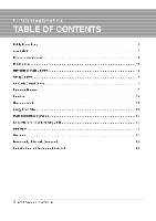
Specifications 8 Dimensions 10 Refrigeration Cycle Diagram 12 Wiring Diagram 13 Electronic Control Device 14 Schematic Diagram 17 Functions 20 Operation Details 23 2-way, 3-way Valve 30 Cycle Troubleshooting Guide 34 Electronic Parts Troubleshooting Guide 35 Installation 42 - LG HMC036KDT1 | Service Manual - Page 3
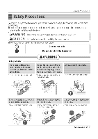
of injury or damage. ■ Meanings of symbol used in this manual are as shown below. Be sure not to do. Be sure to follow the instruction. AWARNING) ■ Installation Do not use a defective or underrated circuit rated breaker or fuse. • There is risk of fire or electric shock. 1 Service Manual 3 - LG HMC036KDT1 | Service Manual - Page 4
and evaporator. For installation, always contact the dealer or an Authorized Service Center. • There is risk of fire, electric shock, explosion, or other appliances near the power cable. ❑o not allow water to run into electric parts. • There is risk of fire or electrical shock. • There is risk of - LG HMC036KDT1 | Service Manual - Page 5
enter the product. • There is risk of physical injury, electric shock, or product fail- • There is risk of fire, electric shock, or product damage. ure. Service Manual 5 - LG HMC036KDT1 | Service Manual - Page 6
ACAUTION check for gas (refrigerant) leakage after installation or repair of product. • Low refrigerant levels may cause failure of to clean. Do not use harsh detergents, solvents, etc. ❑o not touch the metal parts of the product when removing the air filter. They are very sharp! • There is - LG HMC036KDT1 | Service Manual - Page 7
high power until it reaches desired temperature. • And when it reaches the temperature, 0:15 0:20 only the 40% Capacity rotary Operation time (min) compressor operates. Service Manual 7 Indoor Temp (°C) - LG HMC036KDT1 | Service Manual - Page 8
Product Specifications N Product Specifications 1. HMC036KDT1 Item Operation Unit Cooling Capacity Heating Capacity Moisture Removal Power Source x D) dB(A) W A Btu/h.w mm Net. Weight kg Service Valve mm(Inch) Refrigerant(R-22) 9 Airflow Direction Control(Up & Down) Remote Controller Type - LG HMC036KDT1 | Service Manual - Page 9
(W x H x D) dB(A) W A Btu/Irw mm Net. Weight kg Service Valve mm(Inch) Ref rigerant(R-22) g Airflow Direction Control(Up & Down) x 170 Outdoor 870 x 1060 x 320 Indoor 9 Outdoor 78 Liquid 6.35(1/4) Gas 9.52(3/8) 2,500 780 780 at 7.5m 0 L.G.D Wireless 0 0 Service Manual 9 - LG HMC036KDT1 | Service Manual - Page 10
Dimensions Dimensions 1. Indoor Unit H w Tubing hole cover installation plate • • . DIM W H D Lett rear piping A Center •• A e7Ornm Right rear piping A J tenter Amor- 07Ornm MODEL mm mm mm HMC036KDT1, HMH036KDT1 888 287 170 10 MPS Multi Air Conditioner - LG HMC036KDT1 | Service Manual - Page 11
2. Outdoor Unit Dimensions I DIM W H D L1 L2 L3 L4 L5 L6 L7 L8 L9 L10 L11 L7 L6 L8 MODEL mm ill al mm mm mm fri ITI mm mm M M mm mm mm mm mm Gas side 3-way valve Liquid side 2-way valve L9 HMC036KDT1, HMH036KDT1 870 1038 320 360 340 25 1035 25 546 160 160 44 64.5 50 Service Manual 11 - LG HMC036KDT1 | Service Manual - Page 12
Cycle Diagram I Refrigeration Cycle Diagram 1. HMH036KDT1 Indoor Side Outdoor Side 4- WAY Valve x COMP A COMP B 2. HA4C0361CDT1 Indoor Side Outdoor Side U o Q COMP A COMP B 12 MPS Multi Air Conditioner ex) Avow- - - LG HMC036KDT1 | Service Manual - Page 13
RY :RELAY ANIV AWAY VALVE SE -SOLENOID VALVE or ENTT-H1 cenKP`r°wEm °r:71"sEioR2 K 4.1 MAC CC PCB ASSY C THERMISPORCRIRE) THERMISIONAIR) 11 THERIAISTORPSCRAFIGE-O THEFRAISTORPSCSARGEM 3854A24002B Service Manual 13 - LG HMC036KDT1 | Service Manual - Page 14
Electronic Control Device Electronic Control Device Indoor Unit • MAIN P.C.B DC ASM -DCIDC CM-MOTOR Or° COM C OutiANC) POLY-5W 50 COD ACC ir- > DIP 1.111 IFTT177.7177.1 000 0 do1,113A irti oith170.4 rril aFari CH-Tle CM-TM CN- UR CN-U/D 000 0 SVOIF • EE III CN-310 MIWAIMMIZ.1 - LG HMC036KDT1 | Service Manual - Page 15
IMF 0 0 0 0 ,emu J o o o lE o 03U cnel 0-ENE-0 Illlf 1.7.13r O 0 0 Oral o a C. 11 .11,1 8 o Co (11.83 oC) NNW O O ml r 0 m7.1 0 IE O 00 0 COW PCB P/ N 6870A90195A ASM P/N : 6871A20500 I Service Manual 15 - LG HMC036KDT1 | Service Manual - Page 16
Electronic Control Device Display P.C.B ASM CI i= 0 0 16 MPS Multi Air Conditioner - LG HMC036KDT1 | Service Manual - Page 17
I Schematic Diagram Indoor Unit Schematic Diagram I I L 64, HH ax -A- or' S I r z CA! 1 11 - a MS Atx -I th 0 a a s g E Service Manual 17 - LG HMC036KDT1 | Service Manual - Page 18
Schematic Diagram Outdoor Unit w Chu 18 MPS Multi Air Conditioner 0 5 A - LG HMC036KDT1 | Service Manual - Page 19
Schematic Diagram A cRT? EX 0 g L. Eof I ng. vE 1t • El s U0 = El I gig he E2 a ttt Service Manual 19 - LG HMC036KDT1 | Service Manual - Page 20
Functions Functions Indoor Unit Operation ON/OFF by Remote controller Sensing the Room Temperature • Room temperature sensor. (THERMISTOR) Room temperature control • Maintains the room temperature in accordance with the Setting Temp. Starting Current Control • Indoor fan is delayed for 5 seconds - LG HMC036KDT1 | Service Manual - Page 21
ON or Timer OFF Sleep Operation : 1, 2, 3, 4, 5, 6, 7, Off Timer Airflow Direction Control 0 °C To `F Swtiching Button Fan Operation Mode C) : Fan Operates without cooling or heating. Reset • RESET Service Manual 21 - LG HMC036KDT1 | Service Manual - Page 22
on Indicator H fl OUT DOOR Self-diagnosis Function • Error Indicator • The function is to self-diagnoisis airconditioner and express the troubles identifically if there is any trouble. • Error mark is ON/OFF for the operation LED of evaporator body in the same manner as the following table. - If - LG HMC036KDT1 | Service Manual - Page 23
Temp • 25°C 24`C s Intake Intake Air Temp - LG HMC036KDT1 | Service Manual - Page 24
fan is OFF if pipe -temperatures ove-r6.5°C and outdoer-fan-is-ON-if-pipe-temperature-is-belew 0°C. - Outdoor fan is off if any one part is heating overload condition. ulti Air Conditioner - LG HMC036KDT1 | Service Manual - Page 25
select the setting temperature automatically according to the Fuzzy rule. • While in Fuzzroperation, the airflow speed of the indoor fan is automatically selected according perature. Service Manual 25 - LG HMC036KDT1 | Service Manual - Page 26
Operation Details -2)-Fuzzy-Operaiktn-for-BehumIdification • According-to-the-setting-temperature selected-by-Fuzzy-ruler when the intake air temp is 0.5°C or more below the setting temp, the witiptebsor is turned off. When 0.5°C or mute above the presser ied on CompressorCINI3:ern ttingMarni - LG HMC036KDT1 | Service Manual - Page 27
- LG HMC036KDT1 | Service Manual - Page 28
Operation Details ■ Auto Restarting Operation • When the power is restored after a sudden power failure while in appliance operation, the mode before the power failure is kept on the memory and the appliance automatically operates in the mode on the memory. • The slide switch on the main unit of - LG HMC036KDT1 | Service Manual - Page 29
the forced operation position, the error sound "beep-beep beep beep-beep-"Is-made-I0 timtn=to indicate that the remote controtsrarral cannot be received Service Manual 29 - LG HMC036KDT1 | Service Manual - Page 30
MPS Multi Air Conditioner Shaft position Closed (with valve cap) Closed (clockwise) Open (with valve cap) Open (counter-clockwise) Open Open Open Open Service port Closed (with cap) Open (push-pin or with vacuum pump) Closed (with cap) Open (connected manifold gauge) Open (with charging cylinder - LG HMC036KDT1 | Service Manual - Page 31
the manifold gauge to the service port of the gas side valve. - Connect the hose of the gauge with the push pin to the service port. 4. Air purging of side and gas side valve caps and the service port nut. - Use torque wrench to tighten the service port nut to a torque of 1.8kg.m.(4.2kg*m/5.5kg*m) - LG HMC036KDT1 | Service Manual - Page 32
3-way Valve (2) Evacuation (All amount of refrigerant leaked) Indoor unit Liquid side Open 2-Way valve opened position. 2. Connect the vaccum pump to the center hose of the manifold gauge. 3. Connect the service port of the gas side valve to the low side of the gauge. 4. Connect power supply to - LG HMC036KDT1 | Service Manual - Page 33
side valve's service port. This is different from previous procedures. Because you are charging with liquid refrigerant from the gas service port nut. - Use torque wrench to tighten the service port nut to a torque of 1.8 kg.rri.(4.2kg.rn/5.5kg.m.) - Be sure to check for gas leakage. Service Manual - LG HMC036KDT1 | Service Manual - Page 34
Troubleshooting Guide I Cycle Troubleshooting Guide Trouble analysis 1. Check temperature difference between intake and discharge air and operating current. Temp. Difference Operating Current Temp. difference : approx. 0°C Current : less than 80% of rated current All amount of refrigerant - LG HMC036KDT1 | Service Manual - Page 35
Electronic Parts Troubleshooting Guide Electronic Parts Troubleshooting Guide 1. The Outdoor U (* Refer to Electronic Control Device drawing and Schematic diagram.) Turn +5V • Replace ICO2D • Voltage of Micom No. 2, (DC +4.5V over) and Soldering condition. • Replace faulty parts Service Manual 35 - LG HMC036KDT1 | Service Manual - Page 36
Electronic Parts Troubleshooting Guide 2. The product is not operate with the remote contro the wind speed is set to the low speed by force.) Cause by the remote control Caused by other parts except the remote control When the mark( ) is displayed in LCD screen, replace battery. Check the - LG HMC036KDT1 | Service Manual - Page 37
3. When cooling does not operate Electronic Parts Troubleshooting Guide Turn on Main Power Operate "Cooling Mode( * )" by setting the desired temperature of the Diagram. j L. . Good connection Bad connection ..., ,.. Check Outdoor Unit (PCB Ass'y) Correct connection line Service Manual 37 - LG HMC036KDT1 | Service Manual - Page 38
Electronic Parts Troubleshooting Guide 4. When indoor Fan does not operate.(or "ONIOFF" led of display bl line fuse in the outdoor unit Check the connection of CN-MOTOR check the operation of blower by manual Check POLY SIW in indoor PCB Ass'y If it is opened Exchange Indoor PCB Ass'y If it is - LG HMC036KDT1 | Service Manual - Page 39
Electronic Parts Troubleshooting Guide 5, When Vertical - a over does not operate. • Confirm that ) of CN-U/D and GND. If there are no problems after above checks • Confirm the assembly conditions that are catching and interfering parts in the rotation radial of the Vertical Louver Service Manual 39 - LG HMC036KDT1 | Service Manual - Page 40
Electronic Parts Troubleshooting Guide 6. When Heating does not operate Turn ON Main Power Operate "Heating Mode( )" by setting the desired temperature of the remote control is higher than one - LG HMC036KDT1 | Service Manual - Page 41
Electronic Parts Troubleshooting Guide 7. Outdoor unit does not operate at all. Check Outdoor Unit Items • Power Transformer (Outdoor unit) - Input Voltage - Output Voltage 4, • fan, outdoor fan, COMP are not operated. • The unit can be reoperated by On/Off control of Remocon. Service Manual 41 - LG HMC036KDT1 | Service Manual - Page 42
Installation IL-AI Installation (1) Installation of Indoor, Outdoor uni 1) Selection of the best location 1. Indoor unit • There should not be any heat source or steam near the unit. • There should not be any obstacles to prevent the air circulation. • A place where air circulation in the room - LG HMC036KDT1 | Service Manual - Page 43
. The lower left and the right side of Installation Plate Left rear piping 1. he A Right rear piping A4 4.- 070mm Indoor 070mm Wall Outdoor lJ E NE . Service Manual 43 - LG HMC036KDT1 | Service Manual - Page 44
= Improper flaring = r( Surface damaged Cracked Uneven thickness When properly flared, the internal surface flare will evenly shine and be of even thickness. Since the flare part comes into contact with the connectors, carefully check the flare finish. 44 MPS Multi Air Conditioner - LG HMC036KDT1 | Service Manual - Page 45
is clear of its hole. • Turn it clockwise approx. 90 °and remove it. (2) Pull (:) Press I Connecting cable Gas side piping Liquid side piping ❑rain hose Service Manual 45 - LG HMC036KDT1 | Service Manual - Page 46
Installation 6. Indoor unit installation. • Hook the indoor unit onto the upper position of the installation plate. (Engage the two hooks of the rear top of the indoor unit with the upper edge of the installation plate.) Ensure the hooks are properly seated on the installation plate by moving it in - LG HMC036KDT1 | Service Manual - Page 47
Drain hose Press the lower left and right side of the unit against the Installation Plate until the hooks engages with their slots (sound click). Service Manual 47 - LG HMC036KDT1 | Service Manual - Page 48
Installation (3) Connecting Pipings and the cable to Outdoor unit 1) Connecting the pipings to the Outdoor unit 1. Align the center of the pipings and sufficiently tighten the flare nut with fingers. 2. Finally, tighten the flare nut with torque wrench until the wrench clicks. ■ When tightening - LG HMC036KDT1 | Service Manual - Page 49
of wire and wiring method, etc). • Every wire must be connected firmly. • No wire should be allowed to touch refrigerant tubing, the compressor or any moving parts. /?) The connecting cable connected to the indoor and outdoor unit should be complied with the following specifications. (UL recognized - LG HMC036KDT1 | Service Manual - Page 50
- LG HMC036KDT1 | Service Manual - Page 51
field wiring. Wrong wiring can cause the unit to rnisoperate to result in a fire hazard. • Check local electrical codes and any specified wiring instructions or limitations. Connecting cable 2. Attach the Grille onto the cabinet. • Grasp lower the left and right side of the Grille and engage - LG HMC036KDT1 | Service Manual - Page 52
. Taping Drain hose I Plastic Pipings band Connecting cable Power supply cord ((WWI( Trap is required to prevent water from entering into electrical parts. 3. Drain piping ■ The drain hose should point downward for easy drain flow. 0 Downward slope ■ Do not make drain piping. 3. In cases - LG HMC036KDT1 | Service Manual - Page 53
Air Purging of the Pipings and indoor uni The air which contains moisture remaining in the is refrigeration cycle may cause a malfunction on the compressor. 1. Confirm that both the liquid side valve 3-Way r valve 11 Vacuum pump (3 - Low handle V22 (OPEN) Hi- handle (OPEN) Service Manual 53 - LG HMC036KDT1 | Service Manual - Page 54
elevation between indoor units (h2) 7.5m 7.5m (24.6ft) (24.6ft) Indoor Capacity (Btulh) Gas Pipe Size Liquid Standard Length Additional Refrigerant 7.5m 30g1m 12K 1/2" 1/4" (24.611) (0.32oz/ft) A h2 hl hi Oil trap B C h2 I. A CAUTION: Capacity is based on standard length - LG HMC036KDT1 | Service Manual - Page 55
capacity decreases as outdoor temperature decreases. The unit can work below to 14F without unit out or system shut down. Installation 0 Tubing connection Discharge air Service Manual 55 - LG HMC036KDT1 | Service Manual - Page 56
Operation I Operation (1) Name andFu ction-Remote Control (Door Closed) Ili REMOTE CONTROL Signal transmitter Transmits the signals to the room air conditioner. Signal transmitter s iT) OO°F ®TIME ®TIME li4k1B.8B MIBMIT-B79 n0 4L-P wi) *A► LJ 1 Flip up door (closed) 0 START/STOP BUTTON - LG HMC036KDT1 | Service Manual - Page 57
/off). ROOM TEMPERATURE CHECKING BUTTON Used to check the room temperature. 0 °C TO °F SWITCHING BUTTON RESET BUTTON Used prior to resetting time or after replacing batteries. Service Manual 57 - LG HMC036KDT1 | Service Manual - Page 58
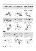
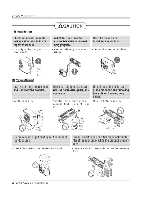
(Indoor unit) Pr Disassembly of the parts (Indoor unit) Warning : Disconnect the unit from power supply before making any checks. Be sure the power switch is set to "OFF". To remove the - LG HMC036KDT1 | Service Manual - Page 59
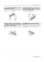
3. To remove the Discharge Grille. • Pull the discharge grille out from the chassis carefully. Disassembly of the parts (Indoor unit) Hook ( 4 ) 0 Hook (4) 0 Screw Screw 4. To remove the Evaporator. • Remove the self-aligning bearing. Bearing 0 Fan motor Screw Cross-flow fan Service Manual 59 - LG HMC036KDT1 | Service Manual - Page 60
Exploded View and Replacement Parts List I Exploded View and Replacement Parts List 1. In•oor Unit I HIVIC036KEITI, HIVIH036KDT1 O CO- .P MM. I ft e CO CO '4 117,7i3r CS) O CO O.1 •rk • -.47- -!' Lc> scoo I cN o 60 MPS Multi Air Conditioner 01 al 0co co C)LI) - LG HMC036KDT1 | Service Manual - Page 61
GRILLE ASSY,INLET SUB Exploded View and Replacement Parts List PART No. HMCO36KDT1 HMH036KDT1 3141A20003D 3141A20003D 3531A10023X 3531A10023X 3531A10099J 5901AR6141C 1H00843A 1H00843A 3531A10032W 3531A10032X SVC CODE R R R R R R R R R R R R R R R R R R R R R Service Manual 61 - LG HMC036KDT1 | Service Manual - Page 62
Exploded View and Replacement Parts List 2. Outdoor Unit HMC036KDT1 '21 / Z///////// //II %V MMIMMN* AIMDAV WMMa%a'a M M aM: off In (m. Co Co l j 62 MPS Multi Air Conditioner - LG HMC036KDT1 | Service Manual - Page 63
- LG HMC036KDT1 | Service Manual - Page 64
Exploded View and Replacement Parts List EIPAHONIKEEI l er... M =A 1V4 r1 A . k NV itl i JILW Ill ' aW4WATigitWAV i ir- A Wv if P 7,x4r,r,r IW/1//K.f , ////77/Yrna` -- W4 WI t/ WM /11\ --wriFIIIrrs-w el off/ . ,. -, .. i f / it - LG HMC036KDT1 | Service Manual - Page 65
- LG HMC036KDT1 | Service Manual - Page 66
-
 1
1 -
 2
2 -
 3
3 -
 4
4 -
 5
5 -
 6
6 -
 7
7 -
8
-
9
-
10
-
11
-
12
-
13
-
14
-
15
-
16
-
17
-
18
-
19
-
20
-
21
-
22
-
23
-
24
-
25
-
26
-
27
-
28
-
29
-
30
-
31
-
32
-
33
-
34
-
35
-
36
-
37
-
38
-
39
-
40
-
41
-
42
-
43
-
44
-
45
-
46
-
47
-
48
-
49
-
50
-
51
-
52
-
53
-
54
-
55
-
56
-
57
-
58
-
59
-
60
-
61
-
62
-
63
-
64
-
65
-
66
 |
 |
MODEL
liFiliC036KDT1
H036KDT1
-BEEGRESERVIeffier
-
T
-
I4EUNIT,
R
"SAFETY
PRECAUTIONS"
IN
THIS
MANUAL
-ONLY
FOR
AUTHORIZED
SERVICE
PERSONNEL.
nternatlonai
iomrort
r
uc
s