LG HMC036KDT1 Service Manual - Page 52
Multi, Conditioner
 |
View all LG HMC036KDT1 manuals
Add to My Manuals
Save this manual to your list of manuals |
Page 52 highlights
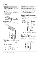
Installation (4) Chec * drai a. (5) For h •in 1. To remove the front panel from the indoor unit, remove the front panel from the indoor unit cabinet. ■ Set the air direction louvers up-and-down to the posi- tion(horizontally) by hand. ■ Remove the securing screws that retain the front panel. Pull the lower left and right sides of the grille toward you and lift it off. (9K Btu models: 2EA, 12K Btu models: 3EA) Pull the right and the left side. re Screw 2. To check the drainage. ■ Pour a glass of water on the evaporator. ■ Ensure the water flows through the drain hose of the indoor unit without any leakage and goes out the drain exit. 1. Form the piping by wrapping the connecting portion of the indoor unit with insulation material and secure it with two kinds of vinyl tapes. ■ If you want to connect an additional drain hose, the end of the drain outlet should be routed above the ground. Secure the drain hose appropriately. 2. In cases where the outdoor unit is installed below the indoor unit perform the following. ■ Tape the piping, drain hose and connecting cable from down to up. ■ Secure the tapped piping along the exterior wall using saddle or equivalent Seal a small opening around the pipings with gum type sealer. Taping Drain hose I Plastic Pipings band Connecting cable Power supply cord ((WWI( Trap is required to prevent water from entering into electrical parts. 3. Drain piping ■ The drain hose should point downward for easy drain flow. 0 Downward slope ■ Do not make drain piping. 3. In cases where the Outdoor unit is installed above the Indoor unit perform the following. ■ Tape the piping and connecting cable from down to up. ■ Secure the taped piping along the exterior wall. Form a trap to prevent water entering the room. ■ Fix the piping onto the wall by saddle or equivalent. Seal a small opening around the pipings with gum type sealer. Trap X Do not raise X -dAicac.lu'"mw'u"ala'rt"ed' X s Tip of drain hosex Less than dipped in water 5Ornm gap Water leakage Water ituv leakage watt' leakage Ditch Trap 52 MPS Multi Air Conditioner
-
 1
1 -
2
-
3
-
4
-
5
-
6
-
7
-
8
-
9
-
10
-
11
-
12
-
13
-
14
-
15
-
16
-
17
-
18
-
19
-
20
-
21
-
22
-
23
-
24
-
25
-
26
-
27
-
28
-
29
-
30
-
31
-
32
-
33
-
34
-
35
-
36
-
37
-
38
-
39
-
40
-
41
-
42
-
43
-
44
-
45
-
46
-
 47
47 -
 48
48 -
 49
49 -
 50
50 -
 51
51 -
 52
52 -
 53
53 -
 54
54 -
 55
55 -
 56
56 -
 57
57 -
58
-
59
-
60
-
61
-
62
-
63
-
64
-
65
-
66
 |
 |
