LG HMC036KDT1 Service Manual - Page 51
instructions
 |
View all LG HMC036KDT1 manuals
Add to My Manuals
Save this manual to your list of manuals |
Page 51 highlights
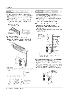
j CAUTION Installation If a power plug is not to be used, provide a circuit breaker between power source and the unit as shown below. Main power source Air Conditioner LI Circuit Breaker Use a circuit breaker or time delay fuse. Model 18k 24k 36k Power source Fuse or breaker Capacity 10,230/208V 15A 10,230/208V 20A 10,230/208V 30A Connect the cable to the indoor unit 1. Connect the wires to the terminals on the control boardindividually according to the outdoor unit connection. • Ensure that the color of the wires of outdoor unit and the terminal No. are the same as those of indoor unit respectively. (Refer to Wiring diagram on pagel 1.) A WARNING • Be sure to refer to the wiring diagram label inside the cover control and carry out the correct field wiring. Wrong wiring can cause the unit to rnisoperate to result in a fire hazard. • Check local electrical codes and any specified wiring instructions or limitations. Connecting cable 2. Attach the Grille onto the cabinet. • Grasp lower the left and right side of the Grille and engage four tabs on the top inside edge of the chassis. • Press the Grille toward the chassis until it will be back into place. Service Manual 51
-
 1
1 -
2
-
3
-
4
-
5
-
6
-
7
-
8
-
9
-
10
-
11
-
12
-
13
-
14
-
15
-
16
-
17
-
18
-
19
-
20
-
21
-
22
-
23
-
24
-
25
-
26
-
27
-
28
-
29
-
30
-
31
-
32
-
33
-
34
-
35
-
36
-
37
-
38
-
39
-
40
-
41
-
42
-
43
-
44
-
45
-
 46
46 -
 47
47 -
 48
48 -
 49
49 -
 50
50 -
 51
51 -
 52
52 -
 53
53 -
 54
54 -
 55
55 -
 56
56 -
57
-
58
-
59
-
60
-
61
-
62
-
63
-
64
-
65
-
66
 |
 |
