LG LMCN185HV Installation Instructions
LG LMCN185HV Manual
 |
View all LG LMCN185HV manuals
Add to My Manuals
Save this manual to your list of manuals |
LG LMCN185HV manual content summary:
- LG LMCN185HV | Installation Instructions - Page 1
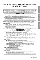
ENGLISH FRANÇAIS ESPAÑOL FLEX MULTI SPLIT INSTALLATION INSTRUCTIONS P/No: MFL39817310 - LG LMCN185HV | Installation Instructions - Page 2
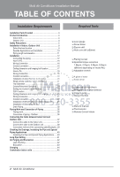
Air Conditioner Installation Manual TABLE OF CONTENTS Installation Requirements Installation Parts Provided 3 Product Introduction 4 Indoor Unit 4 Outdoor Unit 4 Safety Precautions 5 Installation of Indoor, Outdoor Unit 8 Select the best location 8 Seaside Applications and Installation 10 - LG LMCN185HV | Installation Instructions - Page 3
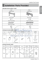
Installation Parts Provided Installation Parts Provided [Standard /Artcool Mirror Type] Type 1 Installation plate Type 2 Installation plate ENGLISH Type "B" screw Type "A" screw (6 EA) Remote control EA Shape Conduit Bracket for gas pipe Screw(M4) 2EA for liquid pipe Installation Manual 3 - LG LMCN185HV | Installation Instructions - Page 4
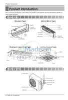
Product Introduction Product Introduction Here is a brief introduction of the indoor and outdoor units. Please see the information specific to your indoor unit type. Indoor Unit [Standard Type] Air inlet Plasma filter (Optional) Grille tab Front grille ON/OFF button [Artcool Mirror Type] Air - LG LMCN185HV | Installation Instructions - Page 5
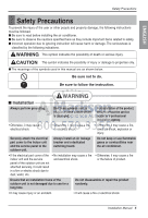
the symbols used in this manual are as shown below. Be sure not to do. Be sure to follow the instruction. WARNING I Installation Always perform grounding. Don . • If the electrical part cover of the • No installation may cause a fire indoor unit and the service and electrical shock. panel - LG LMCN185HV | Installation Instructions - Page 6
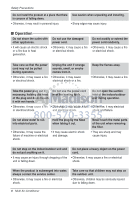
in personal injury. Use caution when unpacking and installing. • Sharp edges may cause injury. I electrical and damage. shock. Never touch the metal parts of the unit when removing the filter. • product is submerged into water, always contact the service center. • Otherwise, it may cause a fire - LG LMCN185HV | Installation Instructions - Page 7
hose to ensure that drain can be securely done. • Otherwise, it may cause water leakage. Install the product so that the noise or hot wind from the outdoor unit may not cause any may damage your properties. • Otherwise, it may cause the failure of appliance or an accident. Installation Manual 7 - LG LMCN185HV | Installation Instructions - Page 8
a place where there are no obstacles in front of the unit. 3. Make sure that condensation drainage can be conveniently routed away. 4. Do not install near a doorway. 5. Ensure the unit is unobstructed, allow proper space on all sides according to the arrows and distance measurements in the figures - LG LMCN185HV | Installation Instructions - Page 9
warm air. 4. Take the air conditioner weight into account and select a place where noise and disturb neighbors. Rooftop Installations: If the outdoor unit is installed on a roof the unit location. Consult local codes regarding rooftop mounting. Installation of Indoor, Outdoor Unit more - LG LMCN185HV | Installation Instructions - Page 10
on the product. Corrosion, particularly on the condenser and evaporator fins, could cause product malfunction or inefficient performance. 3. If outdoor unit is installed close to the seaside, it should avoid direct exposure to the sea wind. 1. Selecting the location(Outdoor Unit) 1) If the outdoor - LG LMCN185HV | Installation Instructions - Page 11
ENGLISH Installation of Indoor, Outdoor Unit Piping length and elevation Multi Piping Type Outdoor Unit Capacity (Btu/h class) 18k Max total A B h2 C h1 D CAUTION: Capacity is based on standard length and maximum allowance length is on the basis of reliability. Installation Manual 11 - LG LMCN185HV | Installation Instructions - Page 12
[Standard /Artcool Mirror Type] Connecting the piping 1. Prepare the indoor unit's piping and drain hose for installation through the wall. 2. Remove the plastic tubing retainer(see the illustration on the right) and pull the tubing and drain hose away from chassis. 3. Route - LG LMCN185HV | Installation Instructions - Page 13
, extend the indoor unit's drain hose. Then attach the drain pipe. Installation Indoor unit tubing Flare nut Pipes Wrench Indoor unit tubing Open-end wrench drain hose Adhesive Vinyl tape(narrow) Installation Information. For left piping. Follow the instruction below. Good case • Press on the - LG LMCN185HV | Installation Instructions - Page 14
(wide) 10. Reroute the pipings and the drain hose across the back of the chassis. 11. Indoor unit installation 1) Remove the spacer. 2) Ensure that the hooks are properly seated on the installation plate by moving it left and right. 3) Press the lower left and right sides of the unit against the - LG LMCN185HV | Installation Instructions - Page 15
use anchor bolts. • Mount the installation plate horizontally by aligning the centerline using caution concerning the location of the installation plate-routing of the wiring to power connections must be done safely. Installation Plate Chassis Hook Type "A" 110(4 11/32) 110(4 - LG LMCN185HV | Installation Instructions - Page 16
Installation Wiring Connection 1. Connect the wires to the terminals on the control board individually according to the outdoor unit connection. • Ensure that the color of the - LG LMCN185HV | Installation Instructions - Page 17
that can support the weight of the unit. • A place where the unit can withstand its vibration. • A place where service can be easily performed. M10 Nut X 4 M10 SP. washer X 4 (Local supply) M10 washer X 4 M10 washer X 4 M10 SP. washer X 4 (Local supply) M10 Nut X 4 Installation Manual 17 - LG LMCN185HV | Installation Instructions - Page 18
the suspension bolts for locking the suspension bolts on the ceiling. • Mount the suspension bolts to the set anchor firmly. • Secure the installation plates onto the suspension bolts (adjust level roughly) using nuts, washers and spring washers. Old building New building 1 Set anchor 2 Plate - LG LMCN185HV | Installation Instructions - Page 19
• The unit must be horizontal or declined to the drain hose connected when finished installation. Ceiling Drainage hole Drain Pump use INSULATION, OTHERS Insulate the joint and tubes completely Insulation Is the unit fully insulated? • Ground Is the unit safely grounded? Installation Manual 19 - LG LMCN185HV | Installation Instructions - Page 20
(1/32 inch). (It may cause the breakdown of the temperature sensor.) 20mm(1/32 inch) * Do not install the cable with a distance of 50m(164ft) or longer. (This can cause communication error.) * When installing the cable, check whether the connector between the remote controller and the product is - LG LMCN185HV | Installation Instructions - Page 21
ENGLISH Wired remote controller switch information Installation Group Control 2 1 SW±GR Group control switch 1. For individual control/Master use 2. For group control/Slave use Ceiling Height/ depends on indoor unit type, when the remote controller is set as slave. Installation Manual 21 - LG LMCN185HV | Installation Instructions - Page 22
before using Trial Operation The trial operation is to check the installation status of the product. The temperature will not be controlled during On/Off button. 4 The trail operation will be shut down automatically after 18 minutes and system will go to the standby mode. 22 Multi Air Conditioner - LG LMCN185HV | Installation Instructions - Page 23
ENGLISH Celsius/Fahrenheit Switching Installation PQRCUCS0C Defrost Preheat Out door Room Temp Total on Central Run MODE TEMP FAN SPEED TEMP 1 If you will automatically release without input after 30 seconds. Defrost Preheat Out door Room Temp Total on Central Run Installation Manual 23 - LG LMCN185HV | Installation Instructions - Page 24
Installation Setting the Central-Control Address Please set the address while using the central controller. You don't need to set address if you don't use central - LG LMCN185HV | Installation Instructions - Page 25
setting will be activated after the temperature display flashes three times. EX) Lo Med Static pressure(mmAq) Model name Step(H/M/L) AMNW09GB1A0 [LMDN095HV] 8.5 CMM(300cfm) 7.5 CMM(265cfm) 6.5 CMM(230cfm) AMNW12GB1A0 [ 122 82 90 99 109 119 75 84 93 103 114 Installation Manual 25 - LG LMCN185HV | Installation Instructions - Page 26
Ceiling dimension and hanging bolt location • The dimensions of the paper model for installation are the same as those of the ceiling opening dimensions. Ceiling from this place. • Ensure enough distance from the cooking room to install the air conditioner in such a place where it may not suck - LG LMCN185HV | Installation Instructions - Page 27
and the ceiling surface Paper model for installation Set screw of paper model (4 pieces) Open the ceiling board along the outer edge of the paper model • The following parts are local purchasing. Hanging Bolt indoor unit. Conduit bracket Connecting Cable Screw Conduit Installation Manual 27 - LG LMCN185HV | Installation Instructions - Page 28
desired location. • Before fixing the wired remote controller cable to the guide slot, remove any clogged part of the case in the direction to install before the installation. 3. After locating the wired remote controller installation board at the desired location, screw the unit firmly. (When there - LG LMCN185HV | Installation Instructions - Page 29
of the connector of the remote controller side and the product side for correct installation. • If you install the extension cable in the opposite direction, the connector will not be connected. • Specification of extension cable: 2547 1007 22# 2 core 3 shield 5 or above. Installation Manual 29 - LG LMCN185HV | Installation Instructions - Page 30
of Decorative Panel The decorative panel has its installation direction. Before installing the decorative panel, always remove the paper template. 1. Remove the packing and take out air inlet grille from front panel. Front grille 2. Remove the Corner - LG LMCN185HV | Installation Instructions - Page 31
5. Fit the corner covers. Installation ENGLISH 6. Open two screws of control panel cover. 7. Connect one display connector and connector: CN-VANE 1,2 8. Close the cover for control box. Screw CN-VANE 1,2 CN-DISPLAY 9. Install the air inlet grille and Filter on the panel. Installation Manual 31 - LG LMCN185HV | Installation Instructions - Page 32
Installation CAUTION: Install certainly the decorative panel. Cool air leakage causes sweating. Water drops fall. Good example Air conditioner unit Bad example Air conditioner unit Air Cool air leakage (no good) Ceiling board Decorative panel Fit the insulator (this part) and be careful for - LG LMCN185HV | Installation Instructions - Page 33
hose should not be curved, neither screwed. The curved or screwed hose may cause a leakage of water. Installation Upward routing not allowed 1/50~1/100 MAX : 700 mm(27 9/16 inch) Flexible drain hose (accessory hose 1/50~1/100 ❈ The figure can be changed according to model. Installation Manual 33 - LG LMCN185HV | Installation Instructions - Page 34
-head height is up to 700mm(27 9/16 inch). So, it must be installed below 700mm(27 9/16 inch). 2. Keep the drain hose downward up to 1/50~1/100 inclination. Prevent any upward flow or reverse flow in any part. 3. 5mm(3/16 inch) or thicker formed thermal insulator is provided for the drain - LG LMCN185HV | Installation Instructions - Page 35
3/8 1.5~1.7 0.06~0.07 1/2 1.6~1.8 0.06~0.07 Firmly hold copper tube in a bar(or die) as indicated dimension in the table above. 5) Check I Compare the flared work with figure. I If flare is noted to be length all round Inclined Surface Cracked Uneven damaged thickness Installation Manual 35 - LG LMCN185HV | Installation Instructions - Page 36
Flaring Work and Connection of Piping Connection of piping - Outdoor Align the center of the piping and sufficiently tighten the flare nut by hand. Connecting pipe order 1) A~D-UNIT gas side pipe 2) A~D-UNIT liquid side pipe Finally, tighten the flare nut with torque wrench until the wrench clicks - LG LMCN185HV | Installation Instructions - Page 37
to change without notice. When installing, refer to the electrical diagram behind Connect the wires according to color codes by referring to the wiring should be comply with the following specifications: ETL recognized and CSA certified comply with the following specifications: ETL recognized and CSA - LG LMCN185HV | Installation Instructions - Page 38
at least 300V for the connection between indoor and outdoor unit. (For example, Type SJO-WA) WARNING: • Be sure to comply with local and national codes while running the wire from the indoor unit to the outdoor unit(size of wire and wiring method, etc). • Every wire must be connected firmly - LG LMCN185HV | Installation Instructions - Page 39
when the connection cable is pulled outside up to a 35 pound weight WARNING: Loose wiring may cause the terminal to overheat or result in . When connecting each power wire to the corresponding terminal, follow instructions "How to connect wiring to the terminals" and fasten the Installation Manual 39 - LG LMCN185HV | Installation Instructions - Page 40
The figure can be changed according to model. Insulating the Pipe and Special Piping Applications drain hose appropriately. In cases where the outdoor unit is installed below the indoor unit perform the following: 1. Tape the from entering into electrical parts. Seal a small opening around the - LG LMCN185HV | Installation Instructions - Page 41
and check whether the product works normally. WARNING: Do not open the top cover or Set the pipe length when operating the product. 1234 SW01N Installation Manual 41 - LG LMCN185HV | Installation Instructions - Page 42
capillary tubing. 5. Water may lead to corrosion of parts in the refrigeration system. Therefore, the indoor/outdoor unit of the tubing(both indoor and outdoor) and both gas and liquid side service valves with soap bubbles. Bubbles indicate a leak. Be sure to wipe off model. 42 Multi Air Conditioner - LG LMCN185HV | Installation Instructions - Page 43
stop the vacuum pump. Air Purging and Evacuation Indoor unit Outdoor unit Finishing the job 1. With a service valve wrench, turn the valve stem of liquid side valve counter-clockwise to fully open the valve. 2. Vacuum pump ❈ The figure can be changed according to model. Installation Manual 43 - LG LMCN185HV | Installation Instructions - Page 44
for line sets longer or shorter than 7.5m(25ft) for each indoor unit. Additional charge(g) = [(A Room Installation Length - Standard Length ) x 0.22 oz/ft + (B Room Installation Length - Standard Length ) x 0.22 oz/ft +.. ] - CF(Correction Factor) x 1.61 oz ❈ CF = Max. number of connectable - LG LMCN185HV | Installation Instructions - Page 45
Capacity (Btu/h class) 9k 12k 18k Model Name AMNW09GDEA0 AMNW12GDEA0 [LMN095HV] [LMN125HV] AMNW09GB1A0 [LMDN095HV] AMNW12GB1A0 [LMDN125HV] AMNW18GB2A0 [LMDN185HV] AMNW12GTRA0 [LMCN125HV] AMNW18GTQA0 [LMCN185HV] Outdoor Unit Capacity (Btu/h class) 18 k 24 k 36 k Installation Manual 45 - LG LMCN185HV | Installation Instructions - Page 46
46 Multi Air Conditioner - LG LMCN185HV | Installation Instructions - Page 47
instructions de ce manuel ne sont pas lues avec soin et respectées, cela peut provoquer un mauvais fonctionnement de l'appareil, un dommage du bien, des blessures personnelles, voire la mort. ATTENTION: Un défaut d'installation, du service suivant les codes électriques locaux un support supplé - LG LMCN185HV | Installation Instructions - Page 48
de l'adresse de commande centrale 24 Fonction ESP 25 Dimension du plafond et emplacement des boulons de support 26 Connexion du câblage 27 Raccordement du tuyau 27 Installation de la commande à distance 28 Installation du panneau décoratif 30 Tuyauterie de drainage 32 Travail d'évasement - LG LMCN185HV | Installation Instructions - Page 49
Installation Parts Provided Installation Parts Provided [Type Standard /Artcool Mirror] Type 1 Plaque d'installation Type 2 Plaque d'installation FRANÇAIS Vis type "B" Vis type "A" (6 EA) Support de la télécommande Vis type "B" Vis type "A" (8 EA) Support de la télécommande [Climatiseur à - LG LMCN185HV | Installation Instructions - Page 50
Description du produit Description du produit Voici une courte introduction des unités intérieure et extérieure. Veuillez lire les informations pertinentes concernant votre type d'unité intérieure. Unité intérieure [Type Standard] Entrée d'air Filtre plasma (en option) Languette de la grille - LG LMCN185HV | Installation Instructions - Page 51
ne pas faire cela. Veillez à suivre les instructions de ce manuel. FRANÇAIS AVERTISSEMENT I Installation Mettez toujours à terre le produit. • l'unité intérieure et le panneau électrique. mauvais fonctionnement de de service de l'unité l'appareil. extérieure ne sont pas bien fixés, cela - LG LMCN185HV | Installation Instructions - Page 52
produit dans un endroit d'où il puisse tomber. • Autrement, vous risquez de blesser quelqu'un. Soyez prudent pendant le déballage et l'installation. • Les bords aiguisés peuvent provoquer des blessures. I Fonctionnement Ne partagez pas la prise avec d'autres appareils. N'utilisez pas un cordon - LG LMCN185HV | Installation Instructions - Page 53
risquez de provoquer un incendie ou un choc électrique. Contactez le service après-vente si le produit est submergé dans l'eau. Veillez à Autrement, vous risquez de susciter des querelles avec les voisins. Après l'installation ou la réparation du produit, veillez toujours à vérifier qu'il n'y - LG LMCN185HV | Installation Instructions - Page 54
de l'unité intérieure et de l'unité extérieure Installation de l'unité intérieure et de l'unité extérieure Lisez au complet et suivez toutes les indications. Choix du meilleur emplacement Unité intérieure 1. Ne - LG LMCN185HV | Installation Instructions - Page 55
sur le toit: Si l'unité extérieure est installée sur la structure du toit, assurez-vous de mettre à niveau l'unité. Assurezvous que la structure du toit et la méthode d'ancrage soient appropriées pour l'emplacement de l'unité. Consultez les codes locaux concernant le montage du toit. Plus de 300 - LG LMCN185HV | Installation Instructions - Page 56
Guide d'installation en bord de mer ATTENTION 1. Les climatiseurs ne devraient pas être installés dans des endroits où sont produits des gaz corrosifs tels que les gaz acides ou alcalins. 2. Ne pas installer sister au vent. • Les dimensions doivent être environ 1,5 fois contacter LG Electronics pour - LG LMCN185HV | Installation Instructions - Page 57
FRANÇAIS Installation de l'unité intérieure et de l'unité extérieure Élévation (246) 25(82) 3(10) 15(49) 7.5(25) 48k Capacité intérieure (Btu/h classe) 9k 12k 18k Dimension des tuyaux Unité : mm(inch) Gaz Liquide 9.52(3/8) 6.35(1/4) 9.52(3/8) 6.35(1/4) 12.7(1/2) 6.35(1/4) Longueur - LG LMCN185HV | Installation Instructions - Page 58
Mirror] Raccordement de la tuyauterie 1. Préparez la tuyauterie et le raccord de drainage de l'unité intérieure pour l'installation à travers le mur. 2. Enlevez le support de fixation plastique de la tuyauterie (voir l'illustration tout à côté) et tirez du tuyau et du raccord de drainage pour - LG LMCN185HV | Installation Instructions - Page 59
Raccord de drainage Adhésif Raccord de drainage de l'unité intérieure Ruban adhésif (étroit) Information concernant l'installation Pour la tuyauterie gauche. Suivez les instructions ci-dessous. Bon exemple • Appuyez sur la partie supérieure de la bride et dépliez doucement les tuyaux vers - LG LMCN185HV | Installation Instructions - Page 60
en essayant de les déplacer à gauche et à droite. 3) Pressez les parties inférieures gauche et droite de l'unité contre la plaque d'installation jusqu'à ce que les crochets soient encastrés dans leurs encoches (vous entendrez alors un déclic). Canalisation pour passage à travers le trou pour - LG LMCN185HV | Installation Instructions - Page 61
généralement dans les murs. Le perçage des murs pour faire passer les tuyaux doit également être effectuer avec précaution. Platine d'installation Crochet de maintien du châssis Type "A" 110(4 11/32) 110(4 11/32) Ø70mm 90(3 17/32) Tuyau arrière gauche 70(2 3/4) Ø70mm Tuyau - LG LMCN185HV | Installation Instructions - Page 62
Installation Connexion du câblage 1. Raccordez les câbles aux bornes du panneau de châssis pour la remettre en position. Câble de connexion Raccordement du tuyau 1. Assemblez le tuyau et le support de tuyau à l'aide de l'écrou. 2. Placez le câble de raccordement dans le bornier de l'unité inté - LG LMCN185HV | Installation Instructions - Page 63
caché dans le plafond] Dimension du plafond et emplacement des fixations Installation de l'unité Installer l'unité correctement en haut POSITION DES ECROUS DU BOITIER • La surface doit être à niveau et doit pouvoir supporter le poids de l'unité. • L'unité doit être montée dans un emplacement - LG LMCN185HV | Installation Instructions - Page 64
érez l'élément d'ancrage et la rondelle dans les boulons de support pour fixer les boulons de support au plafond. • Serrez fortement les boulons de support à l'élément d'ancrage. • Fixez les plaques d'installation aux boulons de support (réglez grosso modo le niveau) à l'aide des écrous, des - LG LMCN185HV | Installation Instructions - Page 65
tre de 19mm(1/32 inch). Vue du front • L'unité doit être horizontalement ou inclinée vers le raccord de drainage à la fin de l'installation. Plafond Trou de drainage Pompe de drainage utilisée ISOLATION, AUTRES Isolez complètement les joints et les conduits. ISOLATION THERMIQUE Toute isolation - LG LMCN185HV | Installation Instructions - Page 66
C07D Main indoor unit Red Yellow Brown LO2K Côté de la télécommande Côté de l'unité intérieure Cadre principal 3 Enlevez le papier d'installation avant d'installer la télécommande de sorte qu'elle puisse être montée au bon endroit. Fixation de la télécommande * N'enfoncez pas la télécommande - LG LMCN185HV | Installation Instructions - Page 67
FRANÇAIS Informations concernant la télécommande câblée Installation Sélection de l'appareil SW±GR 2 1 Sélection du capteur de la température ambiante SW±HI 3 2 1 S/W 1 Sélection commutateur de commande de groupe, vous devez éteindre l'appareil et l'allumer de nouveau. Manuel d'installation 21 - LG LMCN185HV | Installation Instructions - Page 68
I Pas à suivre avant l'utilisation Fonctionnement d'essai Le mode essai sert à vérifier l'état d'installation de l'appareil. La température ne pourra pas être réglée lors du mode essai. L'appareil pourra seulement fonctionner en plusieurs modes tels que le mode - LG LMCN185HV | Installation Instructions - Page 69
FRANÇAIS Alternance Fahrenheit/Celsius Installation PQRCUCS0C Defrost Preheat Out door Room Temp Total on Central Run MODE TEMP FAN SPEED TEMP 1 Si vous voulez changer après 30 secondes sans appui sur une touche. Defrost Preheat Out door Room Temp Total on Central Run Manuel d'installation 23 - LG LMCN185HV | Installation Instructions - Page 70
Installation Réglage de l'adresse de commande centrale Veuillez régler l'adresse lors de l'utilisation de la commande centrale. Vous n'avez pas besoin de régler l'adresse si la - LG LMCN185HV | Installation Instructions - Page 71
ESP La fonction ESP règle le niveau de chaque vitesse de ventilateur. C'est pour une commodité de l'installation. Il est recommandé de ne pas se servir de cette fonction lors de l'utilisation de la télécommande. 105 114 122 82 90 99 109 119 75 84 93 103 114 Manuel d'installation 25 - LG LMCN185HV | Installation Instructions - Page 72
du plafond et emplacement des boulons de support • Les dimensions du gabarit en papier pour l'installation sont les mêmes que celles de à fin d'éviter qu'il ne puisse aspirer les vapeurs d'huile. 2. Évitez d'installer le climatiseur dans des endroits où de l'huile de cuisine ou de la poudre de - LG LMCN185HV | Installation Instructions - Page 73
et le plafond. Gabarit en papier pour l'installation Ensemble de vis du modèle sur papier (4 pièces) Ouvrez le faux plafond tout le long du bord extérieur du gabarit en papier. • Les pièces ci-dessous peuvent être achetées sur place. Boulon de support - W 3/8 ou M10 Écrou - W 3/8 ou M10 - LG LMCN185HV | Installation Instructions - Page 74
Rouge Jaune Noir Câble de la Télécommande ❊ Le câble de la télécommande est connecté comme il vient d'usine. 2. Après avoir fixé le câble à la rainure guide, attachez la carte d'installation de la télécommande à fil sur l'endroit désiré. • Avant de fixer le câble de la télécommande à la rainure - LG LMCN185HV | Installation Instructions - Page 75
érieure 6. Si la distance entre la télécommande à fil et l'unité intérieure est de 10 mètres ou plus, utilisez une rallonge. ATTENTION Pendant l'installation de la télécommande à fil, ne l'encastrez pas dans le mur. (Cela pourrait endommager le capteur de température.) N'installez pas de câble de - LG LMCN185HV | Installation Instructions - Page 76
du panneau décoratif Le panneau décoratif a un sens d'installation qu'il faut respecter. Avant d'installer le panneau décoratif, retirez toujours le gabarit en papier. 1. Retirez l'emballage et retirez la grille d'entrée d'air du panneau avant. Front grille 2. Retirez les caches - LG LMCN185HV | Installation Instructions - Page 77
FRANÇAIS 5. Montez les caches des angles. Installation 6. Dévissez deux vis du cache du panneau de commande. 7. Branchez un connecteur d'affichage et deux connecteurs de . 9. Montez la grille d'entrée d'air et le filtre sur le panneau. Tornillos CN-VANE 1,2 CN-DISPLAY Manuel d'installation 31 - LG LMCN185HV | Installation Instructions - Page 78
Installation ATTENTION : installez le panneau décoratif. Des fuites d'air froid provoquent des suintements des gouttes d'eau tombent. Bon exemple Unité climatiseur Mauvais exemple Unité climatiseur Air - LG LMCN185HV | Installation Instructions - Page 79
25 et tuyaux accessoires. Serre-joint de tuyau Unité intérieure Orifice de drainage de maintenance Ce type de parcours n'est pas permis. • Assurez-vous d'installer un isolant thermique pour la tuyauterie de drainage. Matériau d'isolation thermique : Mousse de polyéthylène de plus de 8mm(5/16 inch - LG LMCN185HV | Installation Instructions - Page 80
Attention 1. La colonne de drainage peut avoir jusqu'à 700mm(27 9/16 inch) de hauteur. Elle doit donc être installée au-dessous de 700mm (27 9/16 inch). 2. Installez le raccord de drainage vers le bas jusqu'à une inclinaison de 1/50~1/100. Évitez tout flux vers - LG LMCN185HV | Installation Instructions - Page 81
enlevé complètement les rebords. (il n'est pas possible de les installer après le travail d'évasement) Écrou évasé Tuyau de cuivre 4) Soutenez fortement le tuyau de cuivre avec une filière d'évasement suivant les dimensions cités dans le tableau d'en bas. Barre Barre Diamètre extérieur - LG LMCN185HV | Installation Instructions - Page 82
Travail d'évasement et raccordement de la tuyauterie Raccordement des tuyaux - Extérieur Alignez le centre du tuyau et serrez correctement le raccord conique à la main. Ordre de raccordement des tuyaux 1) Tuyau côté gaz (unités A à D) 2) Tuyau côté liquide (unités A à D) Pour terminer, serrez le - LG LMCN185HV | Installation Instructions - Page 83
circuit n'est pas sous réserve de modifications sans préavis. Lors de l'installation, lisez le diagramme électrique situé derrière le panneau avant de l'Unité soient débranchés facilement. • Raccordez les câbles suivant les codes de couleur du diagramme du câblage. RECOMMAND: Installez un - LG LMCN185HV | Installation Instructions - Page 84
de faible voltage. 2. Utilisez des câbles électriques calorifuges capables de supporter des températures supérieures à 75°C (167°F). 3. Utilisez des : • Assurez-vous de respecter les codes locaux pour le raccordement de l'unité intérieure à l'unité extérieure (dimension du câble et méthode de câ - LG LMCN185HV | Installation Instructions - Page 85
solidement raccordé. Lors de la connexion de chaque câble d'alimentation au borne correspondant, suivez les instructions "Comment raccorder les câbles aux bornes" et serrez fortement les câbles avec la vis de la boîte à bornes Fixation forte du câble Câble de connexion Manuel d'installation 39 - LG LMCN185HV | Installation Instructions - Page 86
le câble de connexion du bas vers le haut. 2. Assurez la tuyauterie enrubannée au long du mur extérieur á l'aide d'un support ou d'un équivalent. Si l'unité extérieure est installée audessus du niveau de l'unité intérieure, procédez comme il suit. 1. Enveloppez la tuyauterie et le câble de connexion - LG LMCN185HV | Installation Instructions - Page 87
ème fonctionne normalement. AVERTISSEMENT : n'ouvrez pas le couvercle supérieur et ne réglez pas la longueur de tuyau pendant que l'appareil fonctionne. 1234 SW01N Manuel d'installation 41 - LG LMCN185HV | Installation Instructions - Page 88
. Essai de fuites • Raccordez la vanne du collecteur (avec les indicateurs de pression) et le cylindre de gaz nitrogène sec à ce port de service avec les raccordements de charge. ATTENTION: Assurez-vous d'utiliser une vanne de collecteur pour réaliser l'essai de fuites. La vanne du collecteur de la - LG LMCN185HV | Installation Instructions - Page 89
Unité intérieure Unité extérieure Pour finir le travail 1. À l'aide d'une clé pour la vanne de service, tournez la tige de la vanne à liquide dans le sens des aiguilles de l'horloge pour ouvrir complètement la vanne figurent utilisées peuvent ne pas correspondre au modèle Manuel d'installation 43 - LG LMCN185HV | Installation Instructions - Page 90
ligne supérieure ou inférieure à 7,5 m (25 ft) pour chaque unité intérieure. Charge additionnelle (g) = [(Longueur d'installation pièce A - Longueur standard) x 0.22 oz/ft + (Longueur d'installation pièce B - Longueur standard) x 0.22 oz/ft +.. ] - CF (facteur de correction)x 1.61 oz ❈ CF = nombre - LG LMCN185HV | Installation Instructions - Page 91
Btu/h classe) 9k 12k 18k AMNW09GDEA0 [LMN095HV] Model Name AMNW12GDEA0 [LMN125HV] AMNW18GDEL0 [LMN185HV] AMNW09GDER0 [ LMDN125HV] AMNW18GB2A0 [LMDN185HV] AMNW12GTRA0 [LMCN125HV] AMNW18GTQA0 [LMCN185HV] capacité extérieure d'unité(Btu/h classe) l'unité extérieure. Manuel d'installation 45 - LG LMCN185HV | Installation Instructions - Page 92
46 Climatiseur de multi - LG LMCN185HV | Installation Instructions - Page 93
actual y el Código Eléctrico de Canadá Parte 1 CSA C.22.1. • La información contenida en el manual está pensada para ser utilizada por un té y un bastidor metálico. Instale un deflector de aire adecuado. ... en áreas con nieve (para el modelo de bomba de calor): Instale la unidad la unidad exterior - LG LMCN185HV | Installation Instructions - Page 94
de los cables entre las unidades interior 18 Conexión del conducto 18 Installation of Wired Remote Controller 20 Información de interrupt. del mando a distancia fugas de gas ❏ Bomba de vacío ❏ Medidor múltiple ❏ Manual de usuario ❏ Termómetro ❏ Soporte del control remoto 2 Acondicionador de aire - LG LMCN185HV | Installation Instructions - Page 95
ón mando a distancia Cantidad 1 EA 1 EA 8 EA 8 EA 1 EA 1 SET 1 EA Forma Placa de montaje Lado del gas del conducto Tornillo (M4) 2EA Lado del liquido Manual de instalación 3 - LG LMCN185HV | Installation Instructions - Page 96
Presentación del producto Presentación del producto A continuación encontrará una breve presentación de las unidades de interior y exterior. Por favor, consulte la información específica relativa al tipo de su unidad interior. Unidades interiores [Tipo Standard] Entrada de aire Filtro de plasma ( - LG LMCN185HV | Installation Instructions - Page 97
A continuación se muestran los significados de los símbolos utilizados en este manual. No lo haga. Siga las instrucciones. ADVERTENCIA I Instalación Realice siempre cubierta de la parte eléctrica en la unidad interior y el panel de servicio en la unidad exterior. Instale siempre un interruptor - LG LMCN185HV | Installation Instructions - Page 98
justificada. • Podría producirse un incendio o una descarga eléctrica. No instale el aparato en un lugar donde pueda caerse. • De lo contrario, podr una descarga eléctrica y una avería. No permita que entre agua en las partes eléctricas. Sujete la clavija por la cabeza cuando la saque. • De lo - LG LMCN185HV | Installation Instructions - Page 99
. • De lo contrario, podrían producirse disputas con los vecinos. Compruebe siempre si existen pérdidas de Instale la unidad bien nivelada. gas después de instalar o reparar la unidad. • Si no lo hace, podr hace, podría producirse una avería en el aparato o un accidente. Manual de instalación 7 - LG LMCN185HV | Installation Instructions - Page 100
un lugar donde no haya obstáculos frente a la unidad. 3. Asegúrese de que el drenaje de condensación pueda conducirse convenientemente. 4. No instale la unidad cerca de una puerta. 5. Mantenga los espacios indicados por las flechas a la pared, techo, valla u otros obstáculos. 6. Utilice un - LG LMCN185HV | Installation Instructions - Page 101
la radiación de calor del condensador. 2. Mantenga los espacios indicados por las flechas en la parte frontal, posterior y lateral de la unidad. 3. No coloque animales ni plantas expuestos directamente al aire (11 7/16) Más de 600 (23 21/32) Unidad :mm(inch) ESPAÑOL Manual de instalación 9 - LG LMCN185HV | Installation Instructions - Page 102
. Viento del mar Viento del mar 2) En el caso de que instale la unidad exterior en la costa, coloque un cortavientos para protegerlo del viento con LG Electronics para un tratamiento adicional anticorrosión. 2. La limpieza periódica con agua (más de una vez al año) del polvo o las partículas - LG LMCN185HV | Installation Instructions - Page 103
) 20(0.22) 20(0.22) A B h2 C h1 D PRECAUCIÓN: La capacidad está basada en la longitud estándar y la longitud máxima permitida está basada en la fiabilidad. Manual de instalación 11 - LG LMCN185HV | Installation Instructions - Page 104
de conexión Manguera de drenaje Cable de conexión Salida posterior derecha del conducto 7. Instalación de la unidad interior • Cuelgue la unidad interior sobre la parte superior de la placa de instalación. • Inserte el espaciador, etc. entre la unidad interior y la placa de instalación y separe la - LG LMCN185HV | Installation Instructions - Page 105
40~48) 3) Cuando extienda la manguera de drenaje en la unidad interior, instale el conducto de drenaje. Instalación Tubería de la unidad interior Tuerca de . Siga las siguientes instrucciones. Correcto • Presione sobre la parte superior de la abrazadera y desdoble suavemente las tuberías hacia - LG LMCN185HV | Installation Instructions - Page 106
drenaje Conducto Cinta de vinilo (estrecha) Encinte con cinta de vinilo (ancha) 10. Redirija los conductos y la manguera de drenaje hacia la parte posterior del chasis. 11. Instalación de la unidad interior 1) Retire el espaciador. 2) Asegúrese de que los ganchos están fijados adecuadamente sobre - LG LMCN185HV | Installation Instructions - Page 107
Canalización trasera derecha Placa de instalación Enganche del chasis Tipo "A" Ø70mm 133mm Canalización trasera izquierda 100mm Ø70mm Canalización trasera derecha ESPAÑOL Manual de instalación 15 - LG LMCN185HV | Installation Instructions - Page 108
Bloque del terminal del interior 1(L1) 2(L2) 3 4 Cable de conexión ENTRADA DE CORRIENTE EXTERIOR 2. Añada la parrilla a la carcasa. • Sujete la parte inferior derecha e izquierda de la parrilla y coloque cuatro lengüetas en el borde superior interior del chasis. • Presione la parrilla hacia el - LG LMCN185HV | Installation Instructions - Page 109
techo] Dimensiones del techo y situación del perno de suspensión Instalación de la unidad Instale la unidad correctamente en el techo. CASO 1 UBICACIÓN DEL TORNILLO DE SUJECCIÓN • Coloque M10 X 4 Tuerca M10 X 4 Arandela M10 SP X 4 (No incluido) Arandela M10 X 4 Manual de instalación 17 - LG LMCN185HV | Installation Instructions - Page 110
Instalación Cómo fijar • Seleccione y marque la posición para los pernos de sujeción. • Taladre el orificio para el anclaje de fijación en el techo. • Inserte el anclaje de fijación y la arandela en los pernos de suspensión para fijar los pernos de suspensión en el techo. • Monte los pernos de - LG LMCN185HV | Installation Instructions - Page 111
de cierre El tornillo de cierre del compresor está aflojado? • Aislamiento Ha sido completamente aislada la unidad? • Tierra Ha sido seguramente puesta a tierra la unidad? Manual de instalación 19 - LG LMCN185HV | Installation Instructions - Page 112
álelos a intervalos regulares de 20mm(1/32 inch). (Podría causar la avería del sensor de temperatura). * No instale el cable a una distancia de 50m(164ft) o superior. (Esto podría se causa de errores de comunicación.) * Al instalar el cable, compruebe si el conector entre el mando a distancia y el - LG LMCN185HV | Installation Instructions - Page 113
• Cuando cambie el interruptor de selección del producto y el interruptor de control del grupo, la alimentación debe estar conectada para reflejar los cambios. ESPAÑOL Manual de instalación 21 - LG LMCN185HV | Installation Instructions - Page 114
Instalación I Funciones necesarias previas al uso Operación de prueba El funcionamiento de prueba sirve para comprobar la instalación del producto. No se podrá controlar la temperatura durante el funcionamiento de prueba. En cambio, el producto funcionará en varios modos como refrigeración, flujo - LG LMCN185HV | Installation Instructions - Page 115
ajuste. El sistema saldrá automáticamente tras 30 segundos sin entrada de datos. Defrost Preheat Out door Room Temp Total on Central Run ESPAÑOL Manual de instalación 23 - LG LMCN185HV | Installation Instructions - Page 116
Instalación Configuración de la dirección de control central Por favor, establezca la dirección mientras utiliza el mando central. Si usted no utiliza el mando central no tendrá que establecer la dirección. 1 Si desea configurara la dirección en el panel de visualización, presione simultáneamente - LG LMCN185HV | Installation Instructions - Page 117
75 84 94 104 114 69 77 88 99 110 90 97 105 114 122 82 90 99 109 119 75 84 93 103 114 Manual de instalación 25 - LG LMCN185HV | Installation Instructions - Page 118
la capacidad suficiente para todos los gases tóxicos generados en este tipo de lugares. • Asegúrese de que la distancia a la cocina es suficiente e instale el aire acondicionado en un lugar en el que no aspire vapor con grasas. 2. Intente no instalar el aire acondicionado en lugares en los Aire - LG LMCN185HV | Installation Instructions - Page 119
para M10 (accesorio) Tuerca (W3/8 o M10) Mantenga entre 15~18mm (5/8~3/4 inch) entre la parte inferior del aire acondicionado y el techo. Modelo de papel Juego de tornillos del para la instalación unidad interior. Soporte del conducto Cable de conexión Perno Conducto Manual de instalación 27 - LG LMCN185HV | Installation Instructions - Page 120
placa de instalación) Ranura guía (parte posterior de la placa de instalación) Lado de la pared 3. Tras ubicar la placa de instalación del controlador a distancia alámbrico en la posición deseada, atornille firmemente la unidad. (En el caso de unidades empotradas, instale la placa del controlador - LG LMCN185HV | Installation Instructions - Page 121
Podría ocasionar daños en el sensor de temperatura.) No instale el cable con una longitud de 50 m o más. (Esto podría ocasionar errores de comunicación.) • Al instalar la alargadera, compruebe la direcci alargadera: 2547 1007 22#2 con núcleo 3 blindado 5 ó superior. ESPAÑOL Manual de instalación 29 - LG LMCN185HV | Installation Instructions - Page 122
Instalación Instalación del Panel Decorativo El panel decorativo incluye sus propias instrucciones de instalación. Antes de instalar el panel decorativo, retire siempre la plantilla de papel. 1. Retire el material de embalaje y desmonte la rejilla de entrada de aire del panel frontal. Rejilla - LG LMCN185HV | Installation Instructions - Page 123
: Conector de visualización: CN-DISPLAY Conector de control de álabes: CN-VANE 1,2 8. Cierre la cubierta de la caja de control. Tornillos CN-VANE 1,2 CN-DISPLAY 9. Instale la rejilla de entrada de aire y el filtro en el panel - LG LMCN185HV | Installation Instructions - Page 124
de drenaje [Tipo Standard /Artcool Mirror] 1. La manguera de drenaje debe dirigirse hacia abajo para facilitar el drenaje. Inclinación hacia abajo 2. No instale las tuberías de drenaje. No lo levante Agua de drenaje acumulada Aire Fuga de agua Fuga de agua Ondulaciones 32 Acondicionador de - LG LMCN185HV | Installation Instructions - Page 125
Pegue la junta Conexión de la manguera de drenaje Utilice la sujeción (accesorio) Manguera de drenaje 1/50~1/100 ❈ La imagen pueden variar según el modelo Manual de instalación 33 - LG LMCN185HV | Installation Instructions - Page 126
Instalación Atención 1. La altura de drenaje posible es hasta 700mm(27 9/16 inchs). Por lo tanto, deberá instalarse por debajo de 700mm(27 9/16 inchs). 2. Mantenga la manguera de drenaje hacia abajo con una inclinación máxima de 1/50-1/100. Evite cualquier subida o retorno de flujo. 1/50~1/100 MAX - LG LMCN185HV | Installation Instructions - Page 127
flecha roja Liso en toda la superficie El interior brilla sin rasguños = Abocardado incorrecto = Inclinado Superficie Fracturado Grosor no dañada uniforme Longitud igual Manual de instalación 35 - LG LMCN185HV | Installation Instructions - Page 128
Trabajo de abocinado y conexión de las tuberías Conexión de la canalización - Exterior Alinee el centro de la canalización y apriete suficientemente la tuerca cónica manualmente. Orden de conexión de conductos 1) UNIDADES A~E conductos del lado del gas 2) UNIDADES A~E conductos del lado del líquido - LG LMCN185HV | Installation Instructions - Page 129
los cables de acuerdo con los códigos de color consultando el esquema de cableado. Recomendación: Instale un interruptor automático entre la fuente de alimentación y la unidad exterior como se muestra de control utilizando una abrazadera plástica como elemento de fijación. Manual de instalación 37 - LG LMCN185HV | Installation Instructions - Page 130
) 2(L2) 3(C) 3(D) UNIDAD A UNIDAD B UNIDAD C UNIDAD D Cable de alimentación AVISO : 1. Instale por separado la línea de alto y bajo voltaje. 2. Utilice cableado resistente al calor capaz de soportar con la tubería de refrigerante, el compresor o cualquier parte móvil. 38 Acondicionador de aire - LG LMCN185HV | Installation Instructions - Page 131
de alimentación Cable trenzado Terminal redondo Desnudo 10mm(3/8") Cable de conexión Aflojando el tornillo del bloque de terminales Asegurando el cable firmemente Cable de conexión Manual de instalación 39 - LG LMCN185HV | Installation Instructions - Page 132
salida de drenaje debe dirigirse por encima del nivel del terreno. Fije la manguera de drenaje adecuadamente. En caso de que la unidad exterior se instale por debajo de la unidad interior, haga lo siguiente. 1. Encinte las tuberías, la manguera de drenaje y el cable de conexión de abajo hacia arriba - LG LMCN185HV | Installation Instructions - Page 133
le système fonctionne normalement. ADVERTENCIA: No abra la cubierta superior ni ajuste la longitud de la tubería durante el funcionamiento del producto. 1234 SW01N Manual de instalación 41 - LG LMCN185HV | Installation Instructions - Page 134
con jabón líquido. PRECAUCIÓN: Para evitar la entrada de nitrógeno en estado líquido al sistema refrigerante, la parte superior del cilindro debe estar más alta que la parte inferior cuando presurice el sistema. Normalmente, el cilindro se utiliza en posición vertical. AVISO : La prueba de fugas - LG LMCN185HV | Installation Instructions - Page 135
proceso de evacuación para cada unidad interior. Válvula múltiple Manómetro Lo Hi Abrir Cerrar Bomba de vacío ❈ La imagen pueden variar según el modelo Manual de instalación 43 - LG LMCN185HV | Installation Instructions - Page 136
Carga Carga I Cada unidad externa lleva una carga de fábrica (carga en la placa del nombre) para el evaporador y un ajuste de línea de 7,5m (25 pies) para cada línea interior. El ajuste de línea total se utiliza con mayor o menor longitud que la longitud nominal del ajuste de línea de 7.5*ID No. - LG LMCN185HV | Installation Instructions - Page 137
AMNW18GDER0 [LMAN185HV] AMNW09GB1A0 [LMDN095HV] AMNW12GB1A0 [LMDN125HV] AMNW18GB2A0 [LMDN185HV] AMNW12GTRA0 [LMCN125HV] AMNW18GTQA0 [LMCN185HV] Unidad exterior capacidad (Btu/h clase) 18 k 24 k 36 k Combinación conectable O de la unidad exterior. ESPAÑOL Manual de instalación 45
-
 1
1 -
 2
2 -
 3
3 -
 4
4 -
 5
5 -
 6
6 -
 7
7 -
8
-
9
-
10
-
11
-
12
-
13
-
14
-
15
-
16
-
17
-
18
-
19
-
20
-
21
-
22
-
23
-
24
-
25
-
26
-
27
-
28
-
29
-
30
-
31
-
32
-
33
-
34
-
35
-
36
-
37
-
38
-
39
-
40
-
41
-
42
-
43
-
44
-
45
-
46
-
47
-
48
-
49
-
50
-
51
-
52
-
53
-
54
-
55
-
56
-
57
-
58
-
59
-
60
-
61
-
62
-
63
-
64
-
65
-
66
-
67
-
68
-
69
-
70
-
71
-
72
-
73
-
74
-
75
-
76
-
77
-
78
-
79
-
80
-
81
-
82
-
83
-
84
-
85
-
86
-
87
-
88
-
89
-
90
-
91
-
92
-
93
-
94
-
95
-
96
-
97
-
98
-
99
-
100
-
101
-
102
-
103
-
104
-
105
-
106
-
107
-
108
-
109
-
110
-
111
-
112
-
113
-
114
-
115
-
116
-
117
-
118
-
119
-
120
-
121
-
122
-
123
-
124
-
125
-
126
-
127
-
128
-
129
-
130
-
131
-
132
-
133
-
134
-
135
-
136
-
137
 |
 |
ENGLISH
P/No: MFL39817310
FLEX MULTI SPLIT INSTALLATION
INSTRUCTIONS
FRANÇAIS
ESPAÑOL