LG LMCN185HV Installation Instructions - Page 31
Display connector : CN-DISPLAY
 |
View all LG LMCN185HV manuals
Add to My Manuals
Save this manual to your list of manuals |
Page 31 highlights
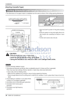
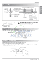
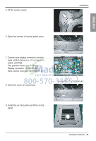
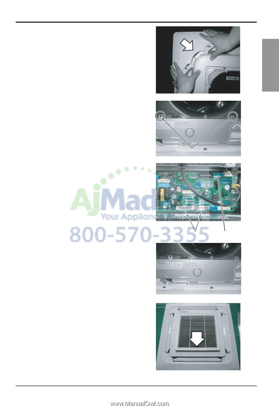
5. Fit the corner covers. Installation ENGLISH 6. Open two screws of control panel cover. 7. Connect one display connector and two vane control connectors of front panel to indoor unit PCB. The position marking on PCB is as: Display connector : CN-DISPLAY Vane control connector: CN-VANE 1,2 8. Close the cover for control box. Screw CN-VANE 1,2 CN-DISPLAY 9. Install the air inlet grille and Filter on the panel. Installation Manual 31
-
 1
1 -
2
-
3
-
4
-
5
-
6
-
7
-
8
-
9
-
10
-
11
-
12
-
13
-
14
-
15
-
16
-
17
-
18
-
19
-
20
-
21
-
22
-
23
-
24
-
25
-
 26
26 -
 27
27 -
 28
28 -
 29
29 -
 30
30 -
 31
31 -
 32
32 -
 33
33 -
 34
34 -
 35
35 -
 36
36 -
37
-
38
-
39
-
40
-
41
-
42
-
43
-
44
-
45
-
46
-
47
-
48
-
49
-
50
-
51
-
52
-
53
-
54
-
55
-
56
-
57
-
58
-
59
-
60
-
61
-
62
-
63
-
64
-
65
-
66
-
67
-
68
-
69
-
70
-
71
-
72
-
73
-
74
-
75
-
76
-
77
-
78
-
79
-
80
-
81
-
82
-
83
-
84
-
85
-
86
-
87
-
88
-
89
-
90
-
91
-
92
-
93
-
94
-
95
-
96
-
97
-
98
-
99
-
100
-
101
-
102
-
103
-
104
-
105
-
106
-
107
-
108
-
109
-
110
-
111
-
112
-
113
-
114
-
115
-
116
-
117
-
118
-
119
-
120
-
121
-
122
-
123
-
124
-
125
-
126
-
127
-
128
-
129
-
130
-
131
-
132
-
133
-
134
-
135
-
136
-
137
 |
 |
Installation
Installation Manual
31
ENGLISH
5. Fit the corner covers.
6. Open two screws of control panel cover.
7. Connect one display connector and two
vane control connectors of front panel to
indoor unit PCB.
The position marking on PCB is as:
Display connector : CN-DISPLAY
Vane control connector: CN-VANE 1,2
8. Close the cover for control box.
9. Install the air inlet grille and Filter on the
panel.
Screw
CN-VANE 1,2
CN-DISPLAY