LG LMCN185HV Installation Instructions - Page 39
Connection method of the connecting cableExample
 |
View all LG LMCN185HV manuals
Add to My Manuals
Save this manual to your list of manuals |
Page 39 highlights
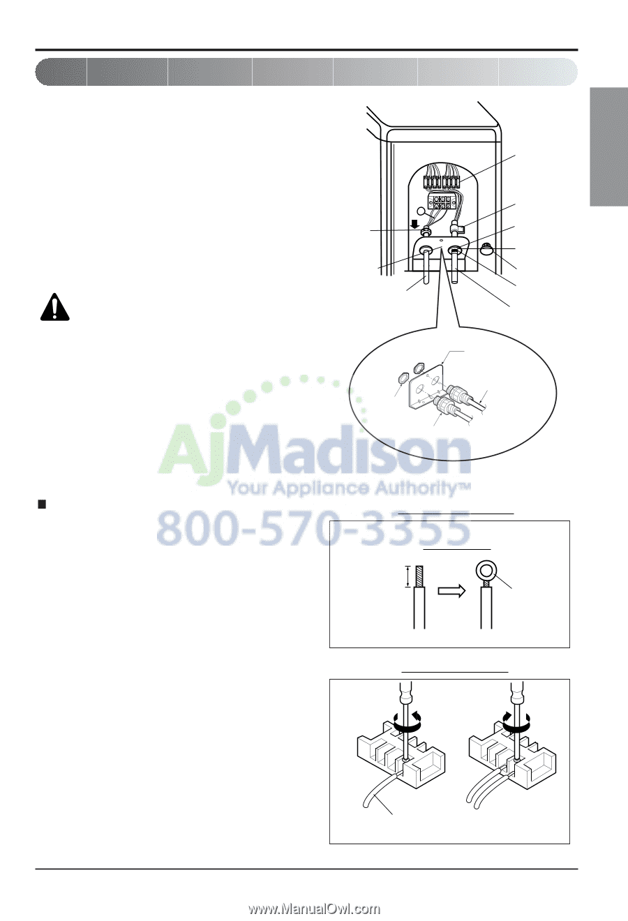
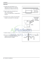
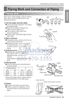
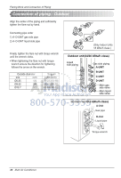
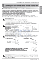
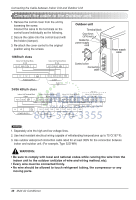
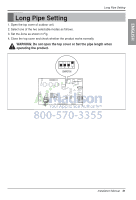
ENGLISH Connecting the Cable between Indoor Unit and Outdoor Unit Connection method of the connecting cable(Example) (1) Remove two-caps on the conduit panel. (for low voltage line) (2) Pull out connection cable through conduit. (3) After conduit to the panel, fix nut to the opposite side of panel. (4) Pass the connection cabel through the hole. (5) Properly connect the cable on the terminal block. (6) Fix the connection cable with cord clamp provided on the unit not to have strain at the terminal when the connection cable is pulled outside up to a 35 pound weight WARNING: Loose wiring may cause the terminal to overheat or result in unit malfunction. A fire hazard may also exist. Therefore, be sure all wiring is tightly connected. When connecting each power wire to the corresponding terminal, follow instructions "How to connect wiring to the terminals" and fasten the wire tightly with the fixing screw of the terminal plate. G Lock nut Conduit panel Power supply line (1Ø, 208/230V) Lock nut (field supply) Conduit (field supply) Terminal block Cord clamp Cap(Reuse) Conduit Hole Cap(Remove) Taping (for sealing) Connecting cable (1Ø, 208/230V) Conduit panel Power supply line or Connecting cable How to connect wiring to the terminals For strand wiring (1) Cut the wire end with a wire cutter or wire- cutting pliers, then strip the insulation to expose the strand wiring about 10 mm(3/8"). (2) Using a screwdriver, remove the terminal screw(s) on the terminal plate. (3) Using a round terminal fastener or pliers, securely clamp each stripped wire end with a round terminal. (4) Position the round terminal wire, and replace and tighten the terminal screw using a screwdriver. Power supply cable Strand wire Round terminal Strip 10 mm(3/8") Connecting Cable Loosening the terminal block screw Fastening the wire tightly Connecting cable Installation Manual 39
-
 1
1 -
2
-
3
-
4
-
5
-
6
-
7
-
8
-
9
-
10
-
11
-
12
-
13
-
14
-
15
-
16
-
17
-
18
-
19
-
20
-
21
-
22
-
23
-
24
-
25
-
26
-
27
-
28
-
29
-
30
-
31
-
32
-
33
-
 34
34 -
 35
35 -
 36
36 -
 37
37 -
 38
38 -
 39
39 -
 40
40 -
 41
41 -
 42
42 -
 43
43 -
 44
44 -
45
-
46
-
47
-
48
-
49
-
50
-
51
-
52
-
53
-
54
-
55
-
56
-
57
-
58
-
59
-
60
-
61
-
62
-
63
-
64
-
65
-
66
-
67
-
68
-
69
-
70
-
71
-
72
-
73
-
74
-
75
-
76
-
77
-
78
-
79
-
80
-
81
-
82
-
83
-
84
-
85
-
86
-
87
-
88
-
89
-
90
-
91
-
92
-
93
-
94
-
95
-
96
-
97
-
98
-
99
-
100
-
101
-
102
-
103
-
104
-
105
-
106
-
107
-
108
-
109
-
110
-
111
-
112
-
113
-
114
-
115
-
116
-
117
-
118
-
119
-
120
-
121
-
122
-
123
-
124
-
125
-
126
-
127
-
128
-
129
-
130
-
131
-
132
-
133
-
134
-
135
-
136
-
137
 |
 |