LG LMCN185HV Installation Instructions - Page 42
Air Purging and Evacuation
 |
View all LG LMCN185HV manuals
Add to My Manuals
Save this manual to your list of manuals |
Page 42 highlights
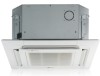
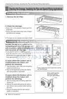
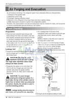
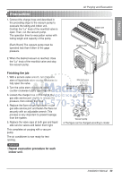
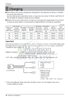
Air Purging and Evacuation Air Purging and Evacuation Air and moisture remaining in the refrigerant system have undesirable effects as indicated below. 1. Pressure in the system rises. 2. Operating current rises. 3. Cooling(or heating) efficiency drops. 4. Moisture in the refrigerant circuit may freeze and block capillary tubing. 5. Water may lead to corrosion of parts in the refrigeration system. Therefore, the indoor/outdoor unit and connecting tube must be checked for leaks, and vacuumed to remove incondensible gas and moisture in the system. Leak Checking Preparation • Check that each tube(both liquid and gas side tubes) between the indoor and outdoor units have been properly connected and all wiring for the test run has been completed. Remove the service valve caps from both the gas and the liquid sides on the outdoor unit. Check that both the liquid and the gas side service valves on the outdoor unit are kept closed at this stage. Leakage test • Connect the manifold valve(with pressure gauges) and dry nitrogen gas cylinder to this service port with charge hoses. CAUTION: Be sure to use a manifold valve for leak testing. The high side manifold valve must always be kept closed. 1. Do a leakage test of all joints of the tubing(both indoor and outdoor) and both gas and liquid side service valves with soap bubbles. Bubbles indicate a leak. Be sure to wipe off the soap with a clean cloth. 2. After the system is found to be free of leaks, relieve the nitrogen pressure by loosening the charge hose connector at the nitrogen cylinder. When the system pressure is reduced to normal, disconnect the hose from the cylinder. Indoor unit Outdoor unit • Pressurize the system to no more than 150 P.S.I.G. with dry nitrogen gas and close the cylinder valve when the gauge reading reached 150 P.S.I.G. Next, test for leaks with liquid soap. CAUTION: To avoid nitrogen entering the refrigerant system in a Manifold valve Pressure Lo Hi gauge liquid state, the top of the cylinder must be higher than its bottom when you pressurize Charge hose the system. Usually, the cylinder is used in a vertical standing position. NOTICE : Leakage testing shoud be done for Nitrogen gas cylinder(in vertical standing position) each indoor unit connection set, separately. ❈ The figure can be changed according to model. 42 Multi Air Conditioner
-
 1
1 -
2
-
3
-
4
-
5
-
6
-
7
-
8
-
9
-
10
-
11
-
12
-
13
-
14
-
15
-
16
-
17
-
18
-
19
-
20
-
21
-
22
-
23
-
24
-
25
-
26
-
27
-
28
-
29
-
30
-
31
-
32
-
33
-
34
-
35
-
36
-
 37
37 -
 38
38 -
 39
39 -
 40
40 -
 41
41 -
 42
42 -
 43
43 -
 44
44 -
 45
45 -
 46
46 -
 47
47 -
48
-
49
-
50
-
51
-
52
-
53
-
54
-
55
-
56
-
57
-
58
-
59
-
60
-
61
-
62
-
63
-
64
-
65
-
66
-
67
-
68
-
69
-
70
-
71
-
72
-
73
-
74
-
75
-
76
-
77
-
78
-
79
-
80
-
81
-
82
-
83
-
84
-
85
-
86
-
87
-
88
-
89
-
90
-
91
-
92
-
93
-
94
-
95
-
96
-
97
-
98
-
99
-
100
-
101
-
102
-
103
-
104
-
105
-
106
-
107
-
108
-
109
-
110
-
111
-
112
-
113
-
114
-
115
-
116
-
117
-
118
-
119
-
120
-
121
-
122
-
123
-
124
-
125
-
126
-
127
-
128
-
129
-
130
-
131
-
132
-
133
-
134
-
135
-
136
-
137
 |
 |