Lexmark M410 User's Guide - Page 236
face of the optional support unit: the tab, the, round hole, and the four square holes.
 |
UPC - 734646261005
View all Lexmark M410 manuals
Add to My Manuals
Save this manual to your list of manuals |
Page 236 highlights
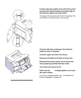
5 Pull the input tray out of the support unit. Remove any packing material and tape from the input tray. 6 Grasp the support unit on each side at opposite corners and move it to the location being used. 7 Notice the following parts located on the top sur- Tab Square Holes face of the optional support unit: the tab, the round hole, and the four square holes. 8 Lift the printer by the handholds or ask someone to help you lift the printer. The bottom surface of the printer has matching holes or feet that accommodate the tab, round hole, and four square holes. Square Holes Round Hole Caution! Make sure your fin- gers are not under the printer when you set it down. 224 Chapter 12: Optional 500-Sheet Drawer
-
 1
1 -
2
-
3
-
4
-
5
-
6
-
7
-
8
-
9
-
10
-
11
-
12
-
13
-
14
-
15
-
16
-
17
-
18
-
19
-
20
-
21
-
22
-
23
-
24
-
25
-
26
-
27
-
28
-
29
-
30
-
31
-
32
-
33
-
34
-
35
-
36
-
37
-
38
-
39
-
40
-
41
-
42
-
43
-
44
-
45
-
46
-
47
-
48
-
49
-
50
-
51
-
52
-
53
-
54
-
55
-
56
-
57
-
58
-
59
-
60
-
61
-
62
-
63
-
64
-
65
-
66
-
67
-
68
-
69
-
70
-
71
-
72
-
73
-
74
-
75
-
76
-
77
-
78
-
79
-
80
-
81
-
82
-
83
-
84
-
85
-
86
-
87
-
88
-
89
-
90
-
91
-
92
-
93
-
94
-
95
-
96
-
97
-
98
-
99
-
100
-
101
-
102
-
103
-
104
-
105
-
106
-
107
-
108
-
109
-
110
-
111
-
112
-
113
-
114
-
115
-
116
-
117
-
118
-
119
-
120
-
121
-
122
-
123
-
124
-
125
-
126
-
127
-
128
-
129
-
130
-
131
-
132
-
133
-
134
-
135
-
136
-
137
-
138
-
139
-
140
-
141
-
142
-
143
-
144
-
145
-
146
-
147
-
148
-
149
-
150
-
151
-
152
-
153
-
154
-
155
-
156
-
157
-
158
-
159
-
160
-
161
-
162
-
163
-
164
-
165
-
166
-
167
-
168
-
169
-
170
-
171
-
172
-
173
-
174
-
175
-
176
-
177
-
178
-
179
-
180
-
181
-
182
-
183
-
184
-
185
-
186
-
187
-
188
-
189
-
190
-
191
-
192
-
193
-
194
-
195
-
196
-
197
-
198
-
199
-
200
-
201
-
202
-
203
-
204
-
205
-
206
-
207
-
208
-
209
-
210
-
211
-
212
-
213
-
214
-
215
-
216
-
217
-
218
-
219
-
220
-
221
-
222
-
223
-
224
-
225
-
226
-
227
-
228
-
229
-
230
-
 231
231 -
 232
232 -
 233
233 -
 234
234 -
 235
235 -
 236
236 -
 237
237 -
 238
238 -
 239
239 -
 240
240 -
 241
241 -
242
-
243
-
244
-
245
-
246
-
247
-
248
-
249
-
250
-
251
-
252
-
253
-
254
-
255
-
256
-
257
-
258
-
259
-
260
-
261
-
262
-
263
-
264
-
265
-
266
-
267
-
268
-
269
-
270
-
271
-
272
-
273
-
274
-
275
-
276
-
277
-
278
-
279
-
280
-
281
-
282
-
283
-
284
-
285
-
286
-
287
-
288
-
289
-
290
-
291
-
292
-
293
-
294
-
295
-
296
-
297
-
298
-
299
-
300
-
301
-
302
-
303
-
304
-
305
-
306
-
307
-
308
-
309
-
310
-
311
-
312
 |
 |

224
Chapter 12: Optional 500-Sheet Drawer
5
Pull the input tray out of the support unit.
Remove any packing material and tape from the
input tray.
6
Grasp the support unit on each side at opposite
corners and move it to the location being used.
7
Notice the following parts located on the top sur-
face of the optional support unit: the tab, the
round hole, and the four square holes.
8
Lift the printer by the handholds or ask someone
to help you lift the printer.
The bottom surface of the printer has matching
holes or feet that accommodate the tab, round hole,
and four square holes.
Caution!
Make sure your fin-
gers are not under the printer
when you set it down.
Tab
Round Hole
Square Holes
Square Holes