Magnavox NB500MGX Owners Manual - Page 9
Front Panel, Rear Panel - remote control
 |
View all Magnavox NB500MGX manuals
Add to My Manuals
Save this manual to your list of manuals |
Page 9 highlights
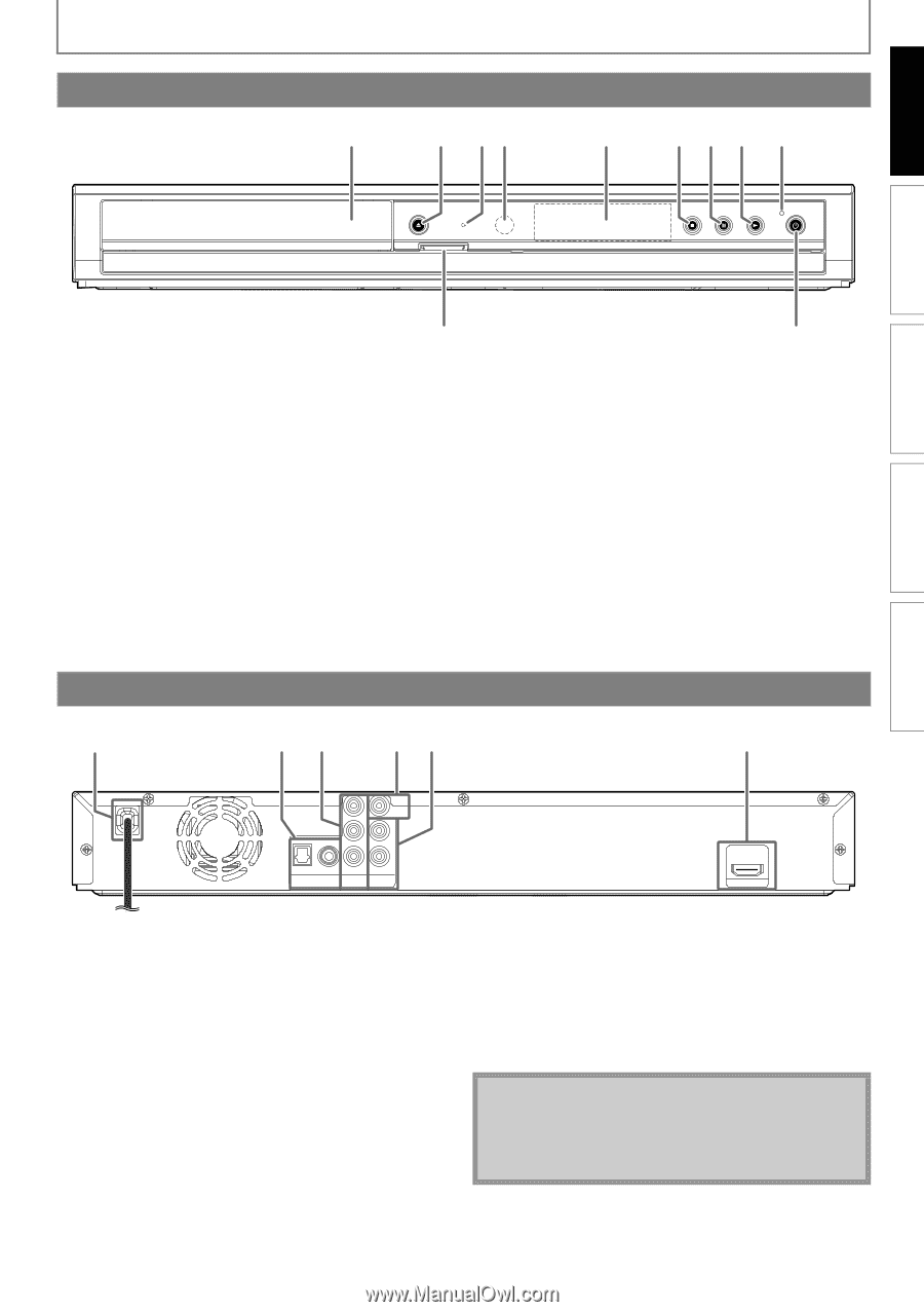
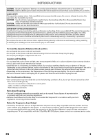
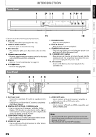
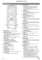
INTRODUCTION Front Panel INTRODUCTION 1 2* 3 4 OPEN/CLOSE DISC IN SD card 5 6 7 8* 9 STOP PAUSE PLAY STANDBY-ON CONNECTIONS PLAYBACK FUNCTION SETUP OTHERS 11 10 (*) The unit can also be turned on by pressing these buttons. 1. Disc tray • Place a disc when opening the disc tray. 2. OPEN/CLOSE A button* • Press to open or close the disc tray. 3. Disc indicator • This indicator lights up in blue when a disc is in this unit. 4. Infrared sensor window • Receive signals from your remote control so that you can control the unit from a distance. 5. Display • Refer to "Front Panel Display" on page 10. 6. STOP C button • Press to stop playback. 7. PAUSE F button • Press to pause playback. 8. PLAY B button* • Press to start or resume playback. 9. STANDBY-ON indicator • This indicator lights up in red when the power is on and turns off when the power is off. 10. STANDBY-ON Q button • Press to turn on the unit, or to turn the unit into the standby mode. (To completely shut down the unit, you must unplug the AC power cord) 11. SD card slot • Insert an SD Memory Card and play back the contents in it. Rear Panel 1 2 3 45 6 Y PB/CB VIDEO OUT L R OPTICAL COAXIAL PR/CR DIGITAL OUT PCM/BITSTREAM COMPONENT VIDEO OUT AUDIO OUT HDMI OUT 1. AC Power Cord • Connect to a standard AC outlet to supply power to this unit. • Unplug this cord from the AC outlet to completely shut down the unit. 2. DIGITAL OUT (OPTICAL / COAXIAL) jacks • Use to connect an AV receiver / amplifier, Dolby Digital / DTS decoder or other device with a digital audio optical / coaxial input jack with a digital audio optical or digital audio RCA cable. 3. COMPONENT VIDEO OUT jacks • Use to connect a TV with component video inputs with an RCA component video cable. 4. VIDEO OUT jack • Use to connect a TV, an AV receiver or other device with an RCA video cable. 5. AUDIO OUT jacks • Use to connect a TV, an AV receiver / amplifier or other device with an RCA audio cable. 6. HDMI OUT jack • Use to connect a TV with an HDMI compatible port with an HDMI cable. Note • Do not touch the inner pins of the jacks on the rear panel. Electrostatic discharge may cause permanent damage to the unit. • This unit does not have the RF modulator. EN 7
-
 1
1 -
2
-
3
-
 4
4 -
 5
5 -
 6
6 -
 7
7 -
 8
8 -
 9
9 -
 10
10 -
 11
11 -
 12
12 -
 13
13 -
 14
14 -
15
-
16
-
17
-
18
-
19
-
20
-
21
-
22
-
23
-
24
-
25
-
26
-
27
-
28
-
29
-
30
-
31
-
32
-
33
-
34
-
35
-
36
-
37
-
38
-
39
-
40
-
41
-
42
-
43
-
44
-
45
-
46
-
47
-
48
-
49
-
50
 |
 |