Maytag MEDE900VJ Use and Care Guide - Page 13
end of
 |
UPC - 883049144764
View all Maytag MEDE900VJ manuals
Add to My Manuals
Save this manual to your list of manuals |
Page 13 highlights
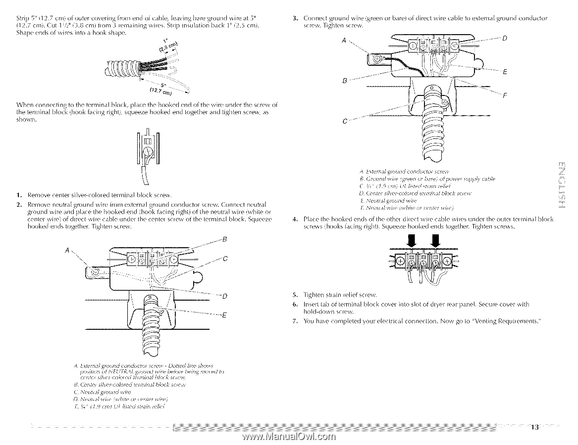
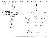
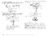
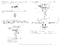
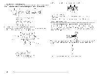
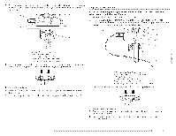
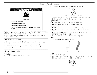
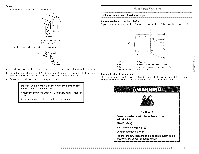
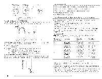
Strip 5" (12.7 cm) of outer covering from end of cable, leaving bare ground wire at 5" (12.7 cm). Cut 1 V2" (3.8 cm) from 3 remaining wires. Strip insulation back 1" (2.5 cm). Shape ends of wires into a hook shape. *" h 3, Connect ground wire (green or bare) of direct wire cable to external ground conductor screw. Tighten screw. When connecting to the terminal block, place the hooked end of the wire under the screw of the terminal block (hook facing right), squeeze hooked end together and tighten screw, as shown. 1, Remove center silver-colored terminal block screw. 2. Remove neutral ground wire from external ground conductor screw. Connect neutral ground wire and place the hooked end (hook facing right) of the neutral wire (white or center wire) of direct wire cable under the center screw of the terminal block. Squeeze hooked ends together. Tighten screw. A. External ground conductor screw B. Ground wire (green or bare) of power supply cable C. ¾" ( 1.9 cm) UL fisted strain refief [i D. Center silver-colored terminal block screw E. Neutral ground wire £ Neutral wire (white or center wire) 4° Place the hooked ends of the other direct wire cable wires under the outer terminal block screws (hooks facing right). Squeeze hooked ends together. Tighten screws. !! !! JjJ D A. External ground conductor screw - Dotted fine shows position of N_UTRA/_ .ground wire ...b. efore being moved to center silver-colored terminal block screw. B. Center siher-colored terminal block screw C. Neutral ground wire D. Neutral wire (white or center wire) E. 3/4" ( 1.9 cm) UL listed strain relief 5. Tighten strain relief screw. 6. Insert tab of terminal block cover into slot of dryer rear panel. Secure cover with hold-down screw. 7. You have completed your electrical connection. Now go to "Venting Requirements."
-
 1
1 -
2
-
3
-
4
-
5
-
6
-
7
-
 8
8 -
 9
9 -
 10
10 -
 11
11 -
 12
12 -
 13
13 -
 14
14 -
 15
15 -
 16
16 -
 17
17 -
 18
18 -
19
-
20
-
21
-
22
-
23
-
24
-
25
-
26
-
27
-
28
-
29
-
30
-
31
-
32
-
33
-
34
-
35
-
36
-
37
-
38
-
39
-
40
-
41
-
42
-
43
-
44
-
45
-
46
-
47
-
48
-
49
-
50
-
51
-
52
-
53
-
54
-
55
-
56
-
57
-
58
-
59
-
60
-
61
-
62
 |
 |