Maytag MER5775RAB Installation Manual - Page 3
Anti-tip, Device, Installation, Instructions - manual
 |
View all Maytag MER5775RAB manuals
Add to My Manuals
Save this manual to your list of manuals |
Page 3 highlights
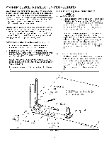
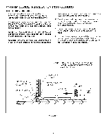
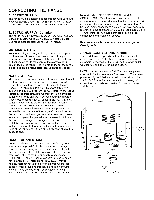
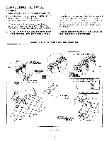
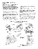
ANTI-TIP DEVICE INSTALLATION INSTRUCTIONS WARNING: A risk of range tip-over exists if the appliance is not installed in accordance with the provided installation instructions. The proper use of this device minimizes the risk of TIP-OVER. In using this device the consumer must still observe the safety precautions as stated in the USE and CARE MANUAL and avoid using the oven door and/or lower drawer as a step stool. Installation instructions are provided for wood and cement in either floor or wall. Any other type of construction may require special installation techniques as deemed necessary to provide adequate fastening of the ANTI-TIP bracket to the floor or wall. The bracket may be installed to engage the left or right rear leveling foot. STEP 1 - Locating The Bracket (See Figure 3) A. Determine where either the right or left "EDGE" of the range will be located and mark the floor or wall. B. Place the BRACKET 9/16" (14.5 mm) from the marked "EDGE" toward center of opening and against the back wall, as shown in figure 3, with orientation hole against wall. C. Use the bracket as a template and mark the required holes, as shown in figure 3 for the type of construction you will be using. D. Free-standing range may be secured to either floor or wall. STEP 2 - Anti-Tip Bracket Installation Options A. Wood Construction: 1. Floor: Locate the center of the two holes identified in figure 3 as "HOLES FOR FLOOR". Drill a 1/8" (3 mm) pilot hole in the center of each hole (a nail or awl may be used if a drill is not available). Secure the ANTI-TIP bracket to the floor with the two screws provided. Proceed to Step 3. . Wall: Locate the center of the two holes identified in figure 3 as "HOLES FOR WALL". Drill an angled 1/8" (3 mm) pilot hole in the center of each hole as shown in figure 4. (A nail or awl may be used if a drill is not available). Secure the ANTI-TIP bracket to the wall with the two screws provided as shown in figure 4. Proceed to STEP 3. B. Cement or Concrete Construction: 1. Suitable screws for concrete construction can be obtained at the hardware store. Drill the required size hole for the hardware obtained into the concrete at the center of the holes identified in figure 3 as "HOLES FOR FLOOR". Secure the ANTI-TIP bracket to the floor. Proceed to STEP 3. 9/16" _ [14.5 ram] / FROMEDGE / J OF RANGE / MARKEDEDGE OF RANGE ORIENTATION HOLE 2SHOLES FOR _- ATTACH ANTI-TIP BRACKET WITH A MINMUM OF fWO (Z) LONG SCREWS TO THE WALL OR FLOOR. ANTI-TIP BRACKET FOOT LEVELIN6 HOLES FOR FLOOR (EACH SIDE) FIGURE 3 -3-
-
 1
1 -
 2
2 -
 3
3 -
 4
4 -
 5
5 -
 6
6 -
 7
7 -
 8
8 -
 9
9 -
10
-
11
-
12
-
13
-
14
-
15
-
16
-
17
-
18
-
19
-
20
-
21
 |
 |
