Maytag MER5775RAB Installation Manual - Page 7
Emo, E, Conddit.
 |
View all Maytag MER5775RAB manuals
Add to My Manuals
Save this manual to your list of manuals |
Page 7 highlights
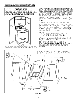
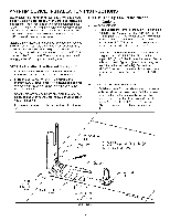
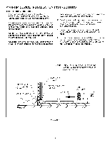
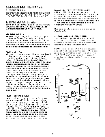
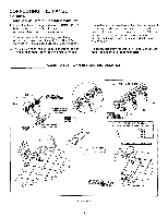
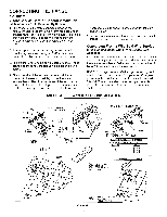
CONNECTING THE RANGE FIGURE 7 4-Wire Service Cord or Conduit Installation (Mobile Homes Or As Required By Codes) 1. The copper ground strap connected between the neutral (middle) post of the main terminal block and the chassis MUST be cut off as shown in figure 7. Save the green ground screw to attach the ground from the 4 wire cord. Only a 4 wire cord or conduit should be used. 2. If bare copper or aluminum wiring is used, attach adapter lugs as shown in figure 7. (See Bare Wire Connection). Torque specifications are shown below. 3. The ground wire from the service cord or conduit must connect to the range chassis using the green ground screw. 4. The white wire of the service cord or conduit must connect to the neutral (middle) post of the main terminal block. The other two wires of the service cord connect to the red and black posts of the main terminal block, respectively. If using bare wire, attach wire to appropriate lug as shown. Torque specifications are shown below. 5. An appropriate strain relief for service cord or conduit MUST be attached to the conduit plate. Conversion From 3-Wire To 4-Wire Service (Free-standing Model With 3-Wire Service Cord Attached), Disconnect range from power. Remove the access cover on back of range and remove the 3-wire service cord from the main terminal block. Follow instructions as outlined in figure 7 to connect the 4-wire service cord. NOTE: Cord replacement - ONLY a power supply cord rated at 240 volts minimum, 40 amperes or 50 amperes power supply cord that is marked for use with nominal 1 3/8" (34.93 mm) diameter connection opening, with closed loop terminals and marked for use with ranges shall be used. ACCEPTABLE - 4 WIRE PLUG INSTALLATION RED WHITE BLACK TERMINAL CONNECTION BLOCK CONDUIT PLATE /' /" / CHASSIS GROUND THIS PORTION GROUNDING STRAP MUST 8E REMOVED, STRAIN RELIEF 1-1t2 (3.8 CM) MINIMUM } MIDDLE WIRE OF SERVICE CORD OR CONDUIT FLOOR _U BARE WIRE CONNECTION RED WHITE ADAPTER / LUGS LOCATED IN LITERATURE HIT BLACK BARF WIRE IOROHF SPF_IFICATIONS tgG ATTACHEOTO TERMINAL BLOCK " 20 IN-LB _LL.ILLA_ ZOLOJ_ 8 35 IN-LB 10A-L14[ERRATIVF INSTAZOIIINA'LTBION ,EMoW,IFCEUONDDIT. > BRACKET, FLIP & RE-ATTACH WITH SMALL HOLE VISIBLE. RECEPTACLE MOUNTED FLUSH TO WALL OUTLET RECEPTACLE TO BE ROTATED AS SHOWN IF NOT FLUSH TO WALL FIGURE 7 -7-
-
 1
1 -
 2
2 -
 3
3 -
 4
4 -
 5
5 -
 6
6 -
 7
7 -
 8
8 -
 9
9 -
 10
10 -
 11
11 -
 12
12 -
13
-
14
-
15
-
16
-
17
-
18
-
19
-
20
-
21
 |
 |
