NEC LCD2490WUXI-BK User Manual - Page 7
continued - manual
 |
UPC - 805736016413
View all NEC LCD2490WUXI-BK manuals
Add to My Manuals
Save this manual to your list of manuals |
Page 7 highlights
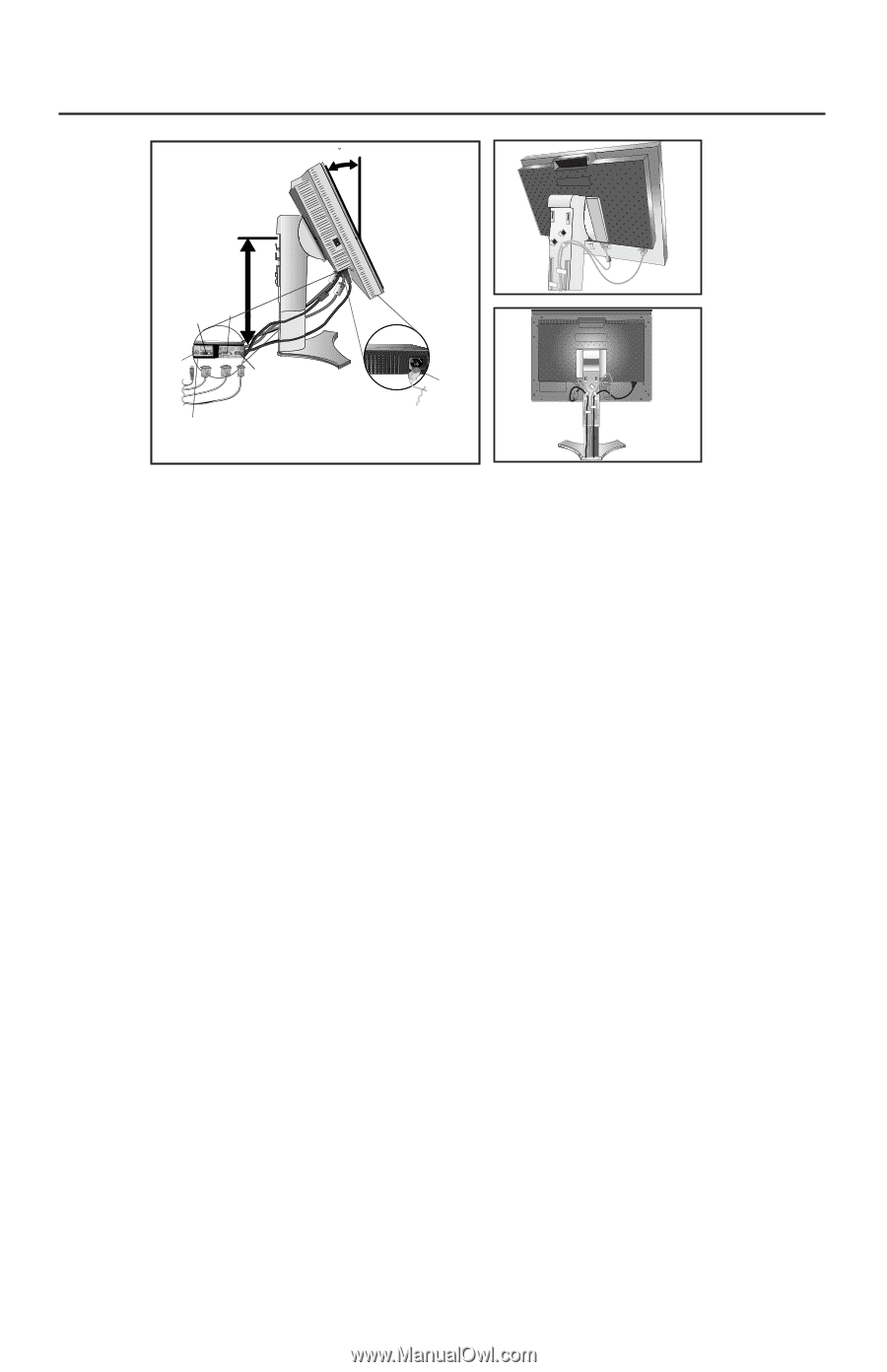
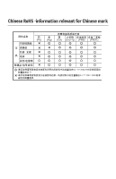
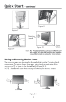
Quick Start - continued Figure 4 30 Tilt Figure 5 Highest Stand Position DVI-D DVI-I DC-OUT D-SUB Power cord (DC out for optional NEC products such as the Soundbar attachment. Do not use this connector unless specified.) Figure 6 Make sure to leave enough slack in the cables so that the Tilt and the Raise and Lower functions of the monitor are not impeded. 6. Hold all of the cables firmly and place the cable cover onto the stand (Figure 8). 7. Slide the Cable Cover back into its correct position (Figure 9). Connect the power cord to power outlet. NOTE: Please refer to the Recommended Use section of this manual for proper selection of power cord. 8. The vacation switch on the left side of the monitor must be in the ON position for the monitor to function (Figure 10). Turn on the monitor using the front power button, then turn on the computer. NOTE: The Vacation Switch is a true on/off switch. If this switch is in the OFF position, the monitor cannot be turned on using the front button. DO NOT turn the vacation switch ON/OFF repeatedly. 9. For Analog input only: Upon initial setup, the No-Touch Auto Adjust feature automatically adjusts the monitor to the optimal settings that are needed for most signal timings. For further adjustments, refer to the Controls section of this User's Manual for a full description of the OSM controls. For download information on the Windows® INF file for your monitor, visit www. necdisplay.com/support. NOTE: If you have any problems, please refer to the Troubleshooting section of this User's Manual. 4
-
 1
1 -
 2
2 -
 3
3 -
 4
4 -
 5
5 -
 6
6 -
 7
7 -
 8
8 -
 9
9 -
 10
10 -
 11
11 -
 12
12 -
13
-
14
-
15
-
16
-
17
-
18
-
19
-
20
-
21
-
22
-
23
-
24
-
25
-
26
-
27
-
28
-
29
-
30
-
31
-
32
-
33
-
34
-
35
-
36
-
37
-
38
-
39
-
40
-
41
-
42
-
43
-
44
-
45
-
46
-
47
-
48
-
49
-
50
-
51
-
52
-
53
-
54
-
55
-
56
-
57
-
58
-
59
-
60
-
61
-
62
-
63
-
64
-
65
-
66
-
67
-
68
-
69
-
70
-
71
-
72
-
73
-
74
-
75
-
76
-
77
-
78
-
79
-
80
-
81
-
82
-
83
-
84
-
85
-
86
-
87
-
88
-
89
-
90
-
91
-
92
-
93
-
94
-
95
-
96
-
97
-
98
-
99
-
100
-
101
-
102
-
103
-
104
-
105
-
106
-
107
-
108
-
109
-
110
-
111
-
112
-
113
-
114
-
115
-
116
-
117
-
118
-
119
-
120
-
121
-
122
-
123
-
124
-
125
-
126
-
127
-
128
-
129
-
130
-
131
-
132
-
133
-
134
-
135
-
136
 |
 |