Netgear FE516 Installation Guide
Netgear FE516 - Hub - Stackable Manual
 |
UPC - 606449000177
View all Netgear FE516 manuals
Add to My Manuals
Save this manual to your list of manuals |
Netgear FE516 manual content summary:
- Netgear FE516 | Installation Guide - Page 1
Installation Guide for the Model FE508 and Model FE516 Fast Ethernet Hubs NETGEAR, Inc. A Bay Networks Company 48105 Warm Springs Blvd. Fremont, CA 94539 USA June 1996 Document Number M-FE500NA-0 - Netgear FE516 | Installation Guide - Page 2
not installed and used in accordance with the instruction manual, it may cause harmful interference to radio user may be required to take appropriate measures. Bestätigung des Herstellers/Importeurs Es wird hiermit bestätigt, daß das NETGEAR Model FE508 and Model FE516 Fast Ethernet Hubs - Netgear FE516 | Installation Guide - Page 3
(information equipment configuring your NETGEAR systems or with post-installation questions or problems, contact your point of purchase representative. To contact customer support or to purchase additional copies of this document or publications for other NETGEAR products, you can contact NETGEAR - Netgear FE516 | Installation Guide - Page 4
Troubleshooting the Hub and Network 4-1 Chapter 5 Network Configuration Examples Ethernet Technology ...5-1 Configuration Examples...5-2 100BASE-TX Shared Repeater 5-2 Building Small Organizations or Remote Offices 5-3 Migrating to 100 Mbps Operation 5-3 Multiport Switch with Fast Ethernet - Netgear FE516 | Installation Guide - Page 5
...A-1 Appendix B Connector Pin Assignments RJ-45 Connector ...B-1 Appendix C Fast Ethernet and Cabling Guidelines Fast Ethernet...C-1 Fast Ethernet Cabling...C-1 Cable Guidelines ...C-2 Cable Lengths...C-2 Cable Specifications ...C-3 Twisted-pair Cables...C-4 Patch Panels and Cables ...C-5 RJ-45 - Netgear FE516 | Installation Guide - Page 6
on your purchase of the NETGEAR™ Model FE508 8-port Fast Ethernet Hub or the Model FE516 16-port Fast Ethernet Hub. These hubs are part of the NETGEAR 500 Series product family, designed to efficiently handle the needs of your 10 and 100 megabits per second (Mbps) network today, and expand to handle - Netgear FE516 | Installation Guide - Page 7
button for simplifying network extension. In the Uplink mode, signals are crossed to allow a straight-through cable to be used on one of the 100BASE-T ports (Port 8 on the Model FE508 hub and Port 16 on the Model FE516 hub) for connection to a 100BASE-T switch or router. • Compact design enables - Netgear FE516 | Installation Guide - Page 8
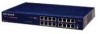
panel of the Model FE508 hub and Figure 2-2 shows the front panel of the Model FE516 hub. 1 = LEDs (Power, Data, and Collision) 2 = RJ-45 ports with Link and RX LEDs on each port 3 = Normal/Uplink push button Figure 2-1. Front panel of the Model FE508 Fast Ethernet hub Physical Description 2-1 - Netgear FE516 | Installation Guide - Page 9
Guide for the Model FE508 and FE516 Fast Ethernet Hubs 1 = LEDs (Power, Data, and Collision) 2 = RJ-45 ports with Link and RX LEDs on each port 3 = Normal/Uplink push button Figure 2-2. Front panel of the Model FE516 Fast Ethernet hub LED Display There are three LEDs on the front panel of the hub - Netgear FE516 | Installation Guide - Page 10
front panel of the Model FE508 hub provides 8 RJ-45 100BASE-TX ports and the Model FE516 provides 16 RJ-45 100BASE-TX ports. These standard RJ-45 connectors accept 2-pair or 4-pair Category 5 unshielded twisted-pair (UTP) copper wiring (100BASE-TX networks require only 2-pair). The RJ-45 interface - Netgear FE516 | Installation Guide - Page 11
an Uplink-wired device (such as a network station or a router). • Configure Ports 8 and 16 for Uplink wiring if the remote end of the cable is connected to a Normal device, such as a 10/100 Mbps switch. The remaining (Normal) ports on the hubs cannot be configured for Uplink wiring. If you are using - Netgear FE516 | Installation Guide - Page 12
Installation Guide for the Model FE508 and FE516 Fast Ethernet Hubs Rear Panel The rear panel of the hub provides two cascade cable connectors, a Terminator LED, two cooling fans, and an AC power receptacle (see Figure 2-4). 1 = Cascade Up and Cascade Down connectors 2 = Terminator LED 3 = - Netgear FE516 | Installation Guide - Page 13
Installation Guide for the Model FE508 and FE516 Fast Ethernet Hubs Cascade Connectors The Model FE508 and Model FE516 Fast Ethernet hubs can be stacked for a maximum of 64 (100 Mbps) ports in a single repeater or collision domain. The stack of four hubs can consist of any combination of Model FE508 - Netgear FE516 | Installation Guide - Page 14
Installation Guide for the Model FE508 and FE516 Fast Ethernet Hubs Terminator LED The Terminator LED, located on the rear panel of the hub, indicates that the built-in terminator in that hub is active. When two or more hubs are cascaded together in a stack, the Terminator LED on the top-most hub - Netgear FE516 | Installation Guide - Page 15
information and procedures on: • Preparing the installation site • Unpacking the equipment • Meeting tool and materials requirements • Installing the hub • Installing multiple hubs 19.68 cm) front and back for service access and maintenance. Front and back NETGEAR 100BASE-T hub. Installation 3-1 - Netgear FE516 | Installation Guide - Page 16
Installation Guide for the Model FE508 and FE516 Fast Ethernet Hubs Wiring hardware Wiring hardware, such as punchdown blocks or patch panels, should be complete before installing the hub. 3-2 Installation - Netgear FE516 | Installation Guide - Page 17
Guide for the Model FE508 and FE516 Fast Ethernet Hubs Package Contents The package should contain the following items: • Model FE508 or Model FE516 Fast Ethernet hub Registration Card and return it to NETGEAR, Inc. Required Tools and Materials To install the hub, you need the following tools and - Netgear FE516 | Installation Guide - Page 18
Guide for the Model FE508 and FE516 Fast Ethernet Hubs Installing a NETGEAR 100BASE-T Hub This section provides information and instructions for installing a single hub in a rack or on a tabletop or any other flat surface. For instructions on installing multiple hubs, see "Installing Multiple Hubs - Netgear FE516 | Installation Guide - Page 19
FE516 hubs (maximum of four hubs to a stack). For instructions on installing multiple hubs, see "Installing Multiple Hubs" later in this chapter. 4. Connect the devices to the ports on the hub using Category 5 UTP wiring and connectors to the RJ-45 connectors. Refer to Appendix C, "Fast Ethernet - Netgear FE516 | Installation Guide - Page 20
Installation Guide for the Model FE508 and FE516 Fast Ethernet Hubs Figure 3-2. Installing the hub in an equipment rack 4. Connect the devices to the ports on the hub using Category 5 UTP wiring and connectors to the RJ-45 connectors. Refer to Appendix C, "Fast Ethernet and Cabling Guidelines," for - Netgear FE516 | Installation Guide - Page 21
Installation Guide for the Model FE508 and FE516 Fast Ethernet Hubs Installing Multiple Hubs This section provides you with information about installing a stack of hubs. This section includes the guidelines for stacking and cascading hubs and the physical requirements for installing multiple hubs. - Netgear FE516 | Installation Guide - Page 22
Installation Guide for the Model FE508 and FE516 Fast Ethernet Hubs Installing and Connecting Multiple Hubs Position the hub you want to be at the top of the stack. For rack installations, you should leave enough space in the rack to expand the stack to four hubs. Each hub occupies 1.0 EIA rack- - Netgear FE516 | Installation Guide - Page 23
Installation Guide for the Model FE508 and FE516 Fast Ethernet Hubs 5. Repeat steps 3 and 4 for all the hubs in the stack. When you have four hubs stacked together, make sure the following conditions exist (see Figure 3-4): − The Cascade Up connector on the top hub is empty. − The Cascade Down - Netgear FE516 | Installation Guide - Page 24
Installation Guide for the Model FE508 and FE516 Fast Ethernet Hubs Verifying Your Installation When installation is complete and power has been applied to the hub, the following conditions should exist: • Power LED on the front panel is on. • Link LED on each connected port should be on. • Data LED - Netgear FE516 | Installation Guide - Page 25
• Link LED on each connected port is lit. • Terminator LED on the rear panel is: − Lit for a single hub. − Lit on the top and bottom hubs in a stack. − Off on the middle hub(s) in the stack. Troubleshooting the Hub and Network Use Table 4-1 to troubleshoot the hub and network. Troubleshooting 4-1 - Netgear FE516 | Installation Guide - Page 26
Installation Guide for the Model FE508 and FE516 Fast Ethernet Hubs Table 4-1. Troubleshooting Symptom No power at hub LEDs Power off In a stack, no power at hub but Terminator LED is on Power off Terminator on Terminator LED on a middle hub in a stack is on Port connection not functioning - Netgear FE516 | Installation Guide - Page 27
Installation Guide for the Model FE508 and FE516 Fast Ethernet Hubs Table 4-1. Troubleshooting (continued) Symptom Collision LED blinking LEDs Collision on Problems with Port 8 on the Model FE508 hub or with Port 16 on the Model FE516 hub Check Collisions are normal on Ethernet networks and - Netgear FE516 | Installation Guide - Page 28
provided by incorporating NETGEAR Ethernet hubs and switches into your network. Examples are given to illustrate the function of the hubs and switches in several configurations that provide those different levels of service to network users. Ethernet Technology When 10BASE-T Ethernet was originally - Netgear FE516 | Installation Guide - Page 29
Guide for the Model FE508 and FE516 Fast Ethernet Hubs Configuration Examples The Model FE508 and Model FE516 hubs are designed to provide flexibility in configuring your network connections. Each hub can be used as a standalone device or can be used with 10 Mbps repeaters, switching hubs - Netgear FE516 | Installation Guide - Page 30
or Model FE516 hub allows power users (for example, those using CAD applications) to be grouped together in the 100 Mbps Fast Ethernet network, isolated from the 10 Mbps network users who need occasional server access. By adding a NETGEAR Model SW502 Ethernet Switch that has one 10 Mbps port and one - Netgear FE516 | Installation Guide - Page 31
Ethernet Hubs Figure 5-2 illustrates 100 Mbps users connected to a Model FE516 hub accessing a common server, integrated with the NETGEAR Model SW502 Ethernet Switch and a Model EN516 Ethernet Hub to form a mixed speed network. Figure 5-2. Migrating to 100 Mbps operation 5-4 Network Configuration - Netgear FE516 | Installation Guide - Page 32
Installation Guide for the Model FE508 and FE516 Fast Ethernet Hubs Multiport Switch with Fast Ethernet Backbone If there is continued congestion on the 10 Mbps shared repeater portion of the network, the Model SW507 Ethernet Switch with six 10 Mbps ports and one 100 Mbps port can be used to segment - Netgear FE516 | Installation Guide - Page 33
Appendix A Technical Specifications This appendix provides technical specifications for the NETGEAR Model FE508 and Model FE516 Fast Ethernet hubs. General Specifications Network Protocol and Standards Compatibility IEEE 802.3u 100BASE-TX, Fast Ethernet IEEE 802.3 CSMA/CD Data Rate 100 Mbps with - Netgear FE516 | Installation Guide - Page 34
Installation Guide for the Model FE508 and FE516 Fast Ethernet Hubs Environmental Specifications Operating temperature: Storage temperature: Operating humidity: Storage humidity: Operating altitude: Storage altitude: Electromagnetic Emissions Meets requirements of: CE mark, commercial FCC Part 15, - Netgear FE516 | Installation Guide - Page 35
This appendix provides information on the RJ-45 connectors that are used for the Model FE508 and Model FE516 Fast Ethernet hubs. RJ-45 Connector The RJ-45 connector is used to connect stations, hubs, and switches through unshielded twisted-pair cable and supports 100 Mbps data transmission - Netgear FE516 | Installation Guide - Page 36
given the increase in packet speed. Fast Ethernet Cabling In a Fast Ethernet network, certain rules and regulations must be followed. This section discusses the following aspects of cabling: • Cable guidelines • Cable lengths within a network • Category 5 specifications • Cross-over and straight - Netgear FE516 | Installation Guide - Page 37
Installation Guide for the Model FE508 and Model FE516 Fast Ethernet Hubs Cable Guidelines Fast Ethernet uses unshielded twisted-pair (UTP) cable, as specified in the IEEE 802.3u standard for 100BASE-T. The specification recommends Category 5 UTP cable consisting of either two-pair or four-pair of - Netgear FE516 | Installation Guide - Page 38
Installation Guide for the Model FE508 and Model FE516 Fast Ethernet Hubs Cable Specifications Table C-1 lists the electrical requirements of the Category 5 cable. Table C-1. Electrical requirements of Category 5 cables Specification Number of pairs Impedance Mutual capacitance at 1 KHz Maximum - Netgear FE516 | Installation Guide - Page 39
Model FE516 Fast Ethernet Hubs Twisted-pair Cables For two devices to communicate, the transmitter of each device must be connected to the receiver of the other device. The cross-over function is usually implemented internally as part of the circuitry in the device. Some repeaters and switch ports - Netgear FE516 | Installation Guide - Page 40
Installation Guide for the Model FE508 and Model FE516 Fast Ethernet Hubs Patch Panels and Cables If you are using patch panels, be sure that they meet the 100BASE-T requirements. NETGEAR recommends Category 5 for all patch cables and work area cables to ensure your UTP patch cable rating meets or - Netgear FE516 | Installation Guide - Page 41
Installation Guide for the Model FE508 and Model FE516 Fast Ethernet Hubs The NEXT loss network designer (for example, new cable can be installed rather than using already installed cable), NETGEAR recommends using Category 5 cables to provide maximum configuration flexibility. C-6 Fast Ethernet - Netgear FE516 | Installation Guide - Page 42
switch, 5-5 shared repeater, 5-2 connectors cascade, 2-6 Cascade Down, 3-7 Cascade Up, 3-7 RJ-45, 2-3, 1, 5 contents, package, 3-2 customer support, iii -E- Ethernet technology, 5-1 -F- fans, 2-7 Fast Ethernet technology, 5-1, 5-5, C-1 features, 1-2 front panel, 2-1 Model FE508 hub, 2-1 Model FE516 - Netgear FE516 | Installation Guide - Page 43
, 3-1 specifications data rate, A-1 electrical, A-1 electromagnetic, A-2 EN 55 022 Declaration of Conformance, ii environmental, A-2 FCC Statement, ii interface, A-1 network protocol, A-1 physical, A-1 Safety Agency approvals, A-2 VCCI Statement, iii stacking hubs, 3-6 switch NETGEAR Ethernet, 5-3 - Netgear FE516 | Installation Guide - Page 44
Installation Guide for the Model FE508 and Model FE516 Fast Ethernet Hubs -T- temperature requirements, 3-1 termination, 3-3, 2 Terminator LED, 2-7 tools required for installation, 3-2 topology star-wired, C-1 troubleshooting table, 4-2 -U- Uplink wiring, 2-4 user requirements, 1-1 -V- ventilation
-
 1
1 -
 2
2 -
 3
3 -
 4
4 -
 5
5 -
 6
6 -
 7
7 -
8
-
9
-
10
-
11
-
12
-
13
-
14
-
15
-
16
-
17
-
18
-
19
-
20
-
21
-
22
-
23
-
24
-
25
-
26
-
27
-
28
-
29
-
30
-
31
-
32
-
33
-
34
-
35
-
36
-
37
-
38
-
39
-
40
-
41
-
42
-
43
-
44
 |
 |
Installation Guide for
the Model FE508 and
Model FE516 Fast
Ethernet Hubs
NETGEAR,
Inc.
A Bay Networks Company
48105 Warm Springs Blvd.
Fremont, CA 94539
USA
June 1996
Document Number
M-FE500NA-0