Netgear FE516 Installation Guide - Page 9
LED Display
 |
UPC - 606449000177
View all Netgear FE516 manuals
Add to My Manuals
Save this manual to your list of manuals |
Page 9 highlights
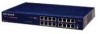
Installation Guide for the Model FE508 and FE516 Fast Ethernet Hubs 1 = LEDs (Power, Data, and Collision) 2 = RJ-45 ports with Link and RX LEDs on each port 3 = Normal/Uplink push button Figure 2-2. Front panel of the Model FE516 Fast Ethernet hub LED Display There are three LEDs on the front panel of the hub and two on each port connector that allow you to identify: • Status of the hub AC power supply • Operational status of the hub • Collision occurrence on an Ethernet segment in a standalone hub or a stack of hubs • Data utilization of the Ethernet segment in a standalone hub or a stack of hubs • Link and RX (receive activity) status for all ports in the hub 2-2 Physical Description
-
 1
1 -
2
-
3
-
 4
4 -
 5
5 -
 6
6 -
 7
7 -
 8
8 -
 9
9 -
 10
10 -
 11
11 -
 12
12 -
 13
13 -
 14
14 -
15
-
16
-
17
-
18
-
19
-
20
-
21
-
22
-
23
-
24
-
25
-
26
-
27
-
28
-
29
-
30
-
31
-
32
-
33
-
34
-
35
-
36
-
37
-
38
-
39
-
40
-
41
-
42
-
43
-
44
 |
 |

Installation Guide for the Model FE508 and FE516 Fast Ethernet Hubs
2-2
Physical Description
1 = LEDs (Power, Data, and Collision)
2 = RJ-45 ports with Link and RX LEDs on each port
3 = Normal/Uplink push button
Figure 2-2.
Front panel of the Model FE516 Fast Ethernet hub
LED Display
There are three LEDs on the front panel of the hub and two on each port connector that allow you to
identify:
•
Status of the hub AC power supply
•
Operational status of the hub
•
Collision occurrence on an Ethernet segment in a standalone hub or a stack of hubs
•
Data utilization of the Ethernet segment in a standalone hub or a stack of hubs
•
Link and RX (receive activity) status for all ports in the hub