Netgear FE516 Installation Guide - Page 10
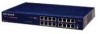
RJ-45 100BASE-TX Ports
 |
UPC - 606449000177
View all Netgear FE516 manuals
Add to My Manuals
Save this manual to your list of manuals |
Page 10 highlights
Installation Guide for the Model FE508 and FE516 Fast Ethernet Hubs Table 2-1 describes each LED on the front panel of the hub. Table 2-1. LED descriptions Type Label State Description Power indicator Power On Power is supplied to the hub. Data Data On Data is being received and transmitted to/from the hub. Collision indicator Collision Blinking There is data collision on the network. Link * Link On A link is established successfully between the hub and the PC or workstation. Off No data link and/or the cable is not connected. Receive * RX Blinking There is incoming data on the port. * Link and RX LEDs are located at the top corners of each RJ-45 port connection. RJ-45 100BASE-TX Ports The front panel of the Model FE508 hub provides 8 RJ-45 100BASE-TX ports and the Model FE516 provides 16 RJ-45 100BASE-TX ports. These standard RJ-45 connectors accept 2-pair or 4-pair Category 5 unshielded twisted-pair (UTP) copper wiring (100BASE-TX networks require only 2-pair). The RJ-45 interface is an 8-pin connector. CAUTION: 100 Mbps operation requires the use of Category 5 UTP wiring with 100 Mbps certified connectors. Refer to Appendix C, "Fast Ethernet and Cabling Guidelines," for more information on cabling. An illustration of the RJ-45 connector and a table of pin assignments are in Appendix B, "Connector Pin Assignments." Table B-1 provides the pin out information for the Normal (MDI-X) RJ-45 connector and the Uplink (MDI) RJ-45 connector. Two LEDs are positioned at the top corners of each RJ-45 connector. The left indicator is the Link LED and the right indicator is the RX (receive) LED. Both LEDs are described in Table 2-1. Physical Description 2-3
-
 1
1 -
2
-
3
-
4
-
 5
5 -
 6
6 -
 7
7 -
 8
8 -
 9
9 -
 10
10 -
 11
11 -
 12
12 -
 13
13 -
 14
14 -
 15
15 -
16
-
17
-
18
-
19
-
20
-
21
-
22
-
23
-
24
-
25
-
26
-
27
-
28
-
29
-
30
-
31
-
32
-
33
-
34
-
35
-
36
-
37
-
38
-
39
-
40
-
41
-
42
-
43
-
44
 |
 |
