Nokia IP290 Installation Guide
Nokia IP290 - Security Appliance Manual
 |
View all Nokia IP290 manuals
Add to My Manuals
Save this manual to your list of manuals |
Nokia IP290 manual content summary:
- Nokia IP290 | Installation Guide - Page 1
Nokia IP290 Security Platform Installation Guide Part No. N450000746 Rev 001 Published August 2008 - Nokia IP290 | Installation Guide - Page 2
NOTE TO USERS This software and hardware is provided by Nokia Inc. as Nokia is a registered trademark of Nokia Corporation. Other products mentioned in this document are trademarks or registered trademarks of their respective holders. 080101 2 Nokia IP290 Security Platform Installation Guide - Nokia IP290 | Installation Guide - Page 3
: Americas Voice: Fax: Asia-Pacific Voice: Fax: https://support.nokia.com/ [email protected] Europe 1-888-361-5030 or 1-613-271-6721 Voice: 1-613-271-8782 Fax: +65-67232999 +65-67232897 +44 (0) 125-286-8900 +44 (0) 125-286-5666 050602 Nokia IP290 Security Platform Installation Guide 3 - Nokia IP290 | Installation Guide - Page 4
4 Nokia IP290 Security Platform Installation Guide - Nokia IP290 | Installation Guide - Page 5
IP290 Appliances 20 2 Installing the Nokia IP290 Appliance 23 Removing the Securing Screws 23 Rack Mounting a Single Nokia IP290 Appliance 24 Rack Mounting Two Nokia IP290 Appliances Side-by-Side 26 3 Performing the Initial Configuration 31 Connecting to the Console Port 31 Connecting Power - Nokia IP290 | Installation Guide - Page 6
Troubleshooting Information 69 A Technical Specifications 73 Physical Dimensions 73 Space Requirements 73 Other Specifications 74 B Compliance Information 75 Declaration of Conformity 75 Compliance Statements 76 FCC Notice (US 77 Index 79 6 Nokia IP290 Security Platform Installation - Nokia IP290 | Installation Guide - Page 7
Tables Table 1 Command-Line Conventions 12 Table 2 Text Conventions 13 Table 3 Appliance Status LEDs 18 Table 4 NIC PCI Frequency 39 Nokia IP290 Security Platform Installation Guide 7 - Nokia IP290 | Installation Guide - Page 8
8 Nokia IP290 Security Platform Installation Guide - Nokia IP290 | Installation Guide - Page 9
24 Figure 6 Installing the Mounting Brackets 25 Figure 7 Single Appliance Installation 26 Figure 8 Power Switch Location 33 Figure 9 Nokia Network Voyager Reference Access Points 37 Figure 10 NIC 43 Figure 15 DIMM Socket Locations 57 Nokia IP290 Security Platform Installation Guide 9 - Nokia IP290 | Installation Guide - Page 10
10 Nokia IP290 Security Platform Installation Guide - Nokia IP290 | Installation Guide - Page 11
About this Guide This guide describes how to install and use the Nokia IP290 security platform. Installation and maintenance should be performed by experienced technicians or Nokia-approved service providers only. This preface provides the following information: „ In This Guide „ Conventions This - Nokia IP290 | Installation Guide - Page 12
> Supply a value. For example: retry-limit 60 -flag A flag is usually an abbreviation for a function, menu, or option name, or for a compiler or preprocessor argument. You must enter a flag exactly as shown, including the preceding hyphen. 12 Nokia IP290 Security Platform Installation Guide - Nokia IP290 | Installation Guide - Page 13
in a command: delete interface if_name Related Documentation You can find this guide in PDF on the Nokia support Web site (https:// support.nokia.com/) and on the Nokia IPSO operating system CD-ROM issued with your Nokia IP290 security platform. Nokia IP290 Security Platform Installation Guide 13 - Nokia IP290 | Installation Guide - Page 14
nokia.com). You can access inline help, the Nokia Network Voyager Reference Guide, and the CLI Reference Guide from Nokia Network Voyager. Check Point documentation is available from the Check Point Web site at: http:// www.checkpoint.com/ 060306 14 Nokia IP290 Security Platform Installation Guide - Nokia IP290 | Installation Guide - Page 15
want high-performance IP routing combined with the industry-leading Check Point VPN-1/ FireWall-1 enterprise security suite. The small size of the IP290 appliances makes them ideal for installations that need to conserve space. As network devices, the IP290 appliances support a comprehensive suite - Nokia IP290 | Installation Guide - Page 16
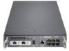
Mbps) Reset switch Console port 00557 Figure 2 Component Locations Rear View Fan vent Power plug Power switch 00558 Built-in Gigabit Ethernet Ports Figure 3 shows the layout of the six built-in 10/100/1000 Ethernet ports and their LEDs. 16 Nokia IP290 Security Platform Installation Guide - Nokia IP290 | Installation Guide - Page 17
1, to establish a modem connection for managing the appliance remotely or out-of-band. Use USB cables with a standard USB A-style connector and pinout for the AUX port. For Nokia approved modem connections, you will need a USB to RS232 adaptor. Nokia IP290 Security Platform Installation Guide 17 - Nokia IP290 | Installation Guide - Page 18
of Nokia IP290 appliances by checking their status LEDs. The system status LEDs are located on the front panel of the appliance, as Figure 4 shows. Figure 4 Appliance Status LEDs Power or Status Caution Critical STATUS POWER FAULT IP290 1 3 5 1000BaseT LINK ACT SLOT 1 LINK ACT RESET - Nokia IP290 | Installation Guide - Page 19
seconds by CPU reset). Site Requirements Before you install a Nokia IP290 appliance, ensure that your computer room or wiring closet conforms to the environmental specifications listed in Appendix A, "Technical Specifications." Product Disposal At the end of its useful life, your appliance and all - Nokia IP290 | Installation Guide - Page 20
use a power cord rated at 6A, 250V, maximum 15 feet long, made of HAR cordage and IEC fittings approved by the country of end use. Managing Nokia IP290 Appliances You can manage Nokia IP290 appliances by using one of the following interfaces: „ Nokia Network Voyager-an SSL-secured, Web-based element - Nokia IP290 | Installation Guide - Page 21
Nokia Horizon Manager-a secure GUI-based software image management application. With Horizon Manager, you can securely install and upgrade the proprietary Nokia IPSO operating system, plus hardware and third-party applications such as Check Point FireWall-1. Horizon Manager can perform installations - Nokia IP290 | Installation Guide - Page 22
1 Overview 22 Nokia IP290 Security Platform Installation Guide - Nokia IP290 | Installation Guide - Page 23
appliance as shown in Figure 5. The screw is required only for shipping, and leaving it in prevents you from sliding the chassis assembly tray out. If you have two appliances in a two-appliance shell, you need to remove one screw from each appliance. Nokia IP290 Security Platform Installation Guide - Nokia IP290 | Installation Guide - Page 24
1 STATUS LINK ACT POWER FAULT AUX RESET CONSOLE 1 IP290 3 5 2 4 6 1000BaseT LINK ACT SLOT 1 STATUS POWER LINK ACT FAULT AUX RESET CONSOLE 1 IP290 3 5 2 4 6 00614a Rack Mounting a Single Nokia IP290 Appliance Before you mount the appliance on the rack, install the two side - Nokia IP290 | Installation Guide - Page 25
3 5 2 4 6 1000BaseT LINK ACT SLOT 1 STATUS POWER LINK ACT FAULT AUX RESET CONSOLE Bracket position B 1 IP290 3 5 2 4 6 00559 You can mount IP290 appliances in a standard 19-inch rack with four mounting screws as Figure 7 shows. Nokia IP290 Security Platform Installation Guide 25 - Nokia IP290 | Installation Guide - Page 26
1000BaseT LINK ACT SLOT 1 STATUS LINK ACT POWER FAULT AUX RESET CONSOLE 1 IP290 3 5 2 4 6 Mounting screws 00560 Rack Mounting Two Nokia IP290 Appliances Side-by-Side The following procedure describes how to install two Nokia IP290 appliances in a 1U rack space. This method does - Nokia IP290 | Installation Guide - Page 27
the appliance counterclockwise until locking arms completely clear the sides of the shell to prevent damage during the installation. 1000BaseT LINK ACT SLOT 1 STATUS POWER FAULT LINK ACT RESET AUX CONSOLE IP290 1 3 5 2 4 6 00565 Nokia IP290 Security Platform Installation Guide 27 - Nokia IP290 | Installation Guide - Page 28
2 Installing the Nokia IP290 Appliance 3. Slide one or two appliances into the shell openings. 1000BaseT LINK ACT SLOT 1 STATUS LINK ACT POWER FAULT AUX RESET CONSOLE 1 IP290 3 5 2 4 6 Filler panel 00563 4. Secure each appliance to the shell by using a screwdriver to turn the locking - Nokia IP290 | Installation Guide - Page 29
two appliances side-by-side in a 1U space. 1000BaseT 1000BaseT LINK ACT SLOT 1 STATUS POWER LINK ACT FAULT AUX RESET CONSOLE 1 IP290 3 5 2 4 6 LINK ACT SLOT 1 STATUS POWER LINK ACT FAULT AUX RESET CONSOLE 1 IP290 3 5 2 4 6 00564 Nokia IP290 Security Platform Installation - Nokia IP290 | Installation Guide - Page 30
2 Installing the Nokia IP290 Appliance 30 Nokia IP290 Security Platform Installation Guide - Nokia IP290 | Installation Guide - Page 31
use DHCP to perform the initial configuration of your Nokia IP290 appliance, you must use a serial console connection (RJ-45 null-modem cable included). After you perform the initial configuration, the console connection is no longer required. Nokia IP290 Security Platform Installation Guide 31 - Nokia IP290 | Installation Guide - Page 32
to the VT100 console or to a system running a terminal-emulation program. Connecting Power and Turning the Power On A power switch and a receptacle for the power cord are located on the power on the back of the appliance as shown in Figure 8. 32 Nokia IP290 Security Platform Installation Guide - Nokia IP290 | Installation Guide - Page 33
the IP290 appliance. Caution To reduce stress on the power supply, after you turn the appliance on, wait at least ten seconds before you turn it off. Likewise, after you turn the power supply off, wait at least ten seconds before you turn it back on. Nokia IP290 Security Platform Installation Guide - Nokia IP290 | Installation Guide - Page 34
appears, then the console prompt appears. The prompt remains on the screen for about five seconds. If you type any character during this time, the appliance activates the Nokia IPSO boot manager. BOOTMGR[0]> 34 Nokia IP290 Security Platform Installation Guide - Nokia IP290 | Installation Guide - Page 35
To reset the incorrect host name and IP address: a. Establish a console connection to the appliance. b. Log into the system using the user name admin and the password password. c. to use as the Nokia Network Voyager system-management interface. Nokia IP290 Security Platform Installation Guide 35 - Nokia IP290 | Installation Guide - Page 36
://support.nokia.com) or on the software CD that was delivered with your appliance. „ Nokia Network Voyager Inline Help-You can access inline help when you use Nokia Network Voyager. Inline help is the context-sensitive information source for Network 36 Nokia IP290 Security Platform Installation - Nokia IP290 | Installation Guide - Page 37
commands section in the CLI Reference Guide for the version of Nokia IPSO you are using. 2. If you log in as a monitor user, you can execute only the show form of commands. That is, you can view configuration settings, but you cannot change them. Nokia IP290 Security Platform Installation Guide - Nokia IP290 | Installation Guide - Page 38
), Horizon Manager concentrates on secure software image, inventory, and management of Nokia IP security appliances. Using Horizon Manager, an administrator can obtain configuration information, upgrade (or downgrade) the operating system, perform application installations, and distribute necessary - Nokia IP290 | Installation Guide - Page 39
or open the appliance. Two-Port Copper Gigabit Ethernet NIC The Nokia IP290 appliance supports Nokia-approved, two-port copper Gigabit Ethernet NICs installed on a PMC expansion slot. The IP290 appliance can accommodate one Gigabit Ethernet NIC. Nokia IP290 Security Platform Installation Guide 39 - Nokia IP290 | Installation Guide - Page 40
NIC faceplate. These NICs are sold by Nokia under the order code NIF4425. After the power is turned on and the cables are connected, the Ethernet Link LEDs on both the appliance and on the remote equipment illuminate to indicate the connection. 40 Nokia IP290 Security Platform Installation Guide - Nokia IP290 | Installation Guide - Page 41
transmits data, the activity LEDs on the appliance illuminate. Copper Gigabit Ethernet NIC Connectors and Cables In Figure 11, the RJ-45 cable output connector is numbered from right to left, with the copper pins facing RX- 7 BI_DD+ 8 BI_DD- Nokia IP290 Security Platform Installation Guide 41 - Nokia IP290 | Installation Guide - Page 42
support) „ Link speed auto advertising „ Tracing through tcpdump „ Compliance with IEEE 802.3z Gigabit Ethernet specification The short-range multi-mode fiber (MMF) fiber-optic Gigabit Ethernet NICs in the IP290 run on Nokia IPSO v4.0.1 or higher. 42 Nokia IP290 Security Platform Installation - Nokia IP290 | Installation Guide - Page 43
Using Nokia Network Voyager" on page 36. Figure 13 shows the front panel details for the two-port short-range (1000 BASE-SX) fiber-optic Gigabit Ethernet NIC you can use in IP290 appliance. 50 micron-type cable provides longer transmission reach. Nokia IP290 Security Platform Installation Guide 43 - Nokia IP290 | Installation Guide - Page 44
IP290 Appliance Network Interface Cards For long-range NICs, to connect the fiber-optic Gigabit Ethernet NIC to other network components, use a single-mode, fiber-optic cable with an LC connector for each NIC interface. The destination end loss. 44 Nokia IP290 Security Platform Installation Guide - Nokia IP290 | Installation Guide - Page 45
Cards Your Nokia IP290 appliance comes with any network interface cards (NICs) you ordered already installed. All NICs installed in the appliance are housed in PMC expansion slots. You should have a working knowledge of networking equipment before you attempt to service a appliance. This chapter - Nokia IP290 | Installation Guide - Page 46
need to manually disconnect power for this procedure. Any servicing of the appliance should be completed with the chassis tray assembly fully removed from the appliance. To install a network interface card 1. Use Nokia Network Voyager or command-line interface (CLI) to perform an orderly shutdown - Nokia IP290 | Installation Guide - Page 47
forward, and completely remove the chassis to expose the motherboard components. 1000BaseT LINK ACT SLOT 1 STATUS POWER LINK ACT FAULT AUX RESET CONSOLE 1 IP290 3 5 2 4 6 6. Place the chassis tray assembly on a table top. 00563 Nokia IP290 Security Platform Installation Guide 47 - Nokia IP290 | Installation Guide - Page 48
screws. SLOT 1 STATUS POWER FAULT AUX RESET CONSOLE 1 IP290 3 5 2 4 6 00570 If you are installing a NIC in an unoccupied slot, remove the blank bezel that occupies the space in the appliance front panel and retain it for future use. 48 Nokia IP290 Security Platform Installation Guide - Nokia IP290 | Installation Guide - Page 49
toward the chassis tray assembly. 1000BaseT LINK ACT LINK ACT SLOT 1 STATUS POWER FAULT AUX RESET CONSOLE 1 IP290 3 5 2 4 6 00572 Make sure that the NIC edge is completely seated into the connectors on the chassis tray assembly. Nokia IP290 Security Platform Installation Guide 49 - Nokia IP290 | Installation Guide - Page 50
LINK ACT SLOT 1 STATUS POWER LINK ACT FAULT AUX RESET CONSOLE 1 IP290 3 5 2 4 6 00571 10. From beneath the chassis tray assembly, screw in the bezel retaining screws. 11. Slide the chassis tray assembly back into the appliance. 50 Nokia IP290 Security Platform Installation Guide - Nokia IP290 | Installation Guide - Page 51
Cards.". Use Network Voyager to access detailed port information. For information about accessing Network Voyager, see "Using Nokia Network Voyager" on page 36. You can also use the IPSO tcpdump command to examine the track on a specific port. Nokia IP290 Security Platform Installation Guide 51 - Nokia IP290 | Installation Guide - Page 52
5 Installing and Replacing Network Interface Cards 52 Nokia IP290 Security Platform Installation Guide - Nokia IP290 | Installation Guide - Page 53
drive is not included in the standard package. When you purchase your IP290 appliance, you can order one hard disk drive for factory installation or order one later and install it yourself. This section describes how to install a hard-disk drive. Nokia IP290 Security Platform Installation Guide 53 - Nokia IP290 | Installation Guide - Page 54
shutdown of the IP290 appliance. For information about how to access Network Voyager and the related reference materials, see "Using Nokia Network Voyager" on page 36. 2. Turn off the power to the IP290 appliance. 3. Remove the power cord. 54 Nokia IP290 Security Platform Installation Guide - Nokia IP290 | Installation Guide - Page 55
shipping screw from the back of the appliance. For details, see Figure 5 on page 24. 1000BaseT LINK ACT SLOT 1 STATUS LINK ACT POWER FAULT AUX RESET CONSOLE 1 IP290 3 5 2 4 6 6. Place the chassis tray assembly on a table top. Nokia IP290 Security Platform Installation Guide 00563 55 - Nokia IP290 | Installation Guide - Page 56
Memory The appliance has two dual inline memory-module (DIMM) sockets that are double data rate (DDR2), which perform at high speed. This section describes how to upgrade or replace the memory by using a Nokia-approved memory upgrade kit. 56 Nokia IP290 Security Platform Installation Guide - Nokia IP290 | Installation Guide - Page 57
replace your appliance memory, you need: „ Physical access to the appliance „ Nokia memory upgrade kit „ Access to the appliance by using Nokia Network Voyager or command-line interface (CLI) „ A Phillips-head screwdriver „ Grounding wrist strap Nokia IP290 Security Platform Installation Guide 57 - Nokia IP290 | Installation Guide - Page 58
IP290 1 3 5 1000BaseT LINK ACT SLOT 1 LINK ACT RESET AUX CONSOLE 2 4 6 Chassis tray assembly retaining screws 00557 5. Slide the chassis tray assembly forward and completely remove the chassis to expose the motherboard components. 58 Nokia IP290 Security Platform Installation Guide - Nokia IP290 | Installation Guide - Page 59
shipping screw from the back of the appliance. For details, see Figure 5 on page 24. 1000BaseT LINK ACT SLOT 1 STATUS LINK ACT POWER FAULT AUX RESET CONSOLE 1 IP290 3 5 2 4 6 00563 6. To properly aligned before you insert the DIMM. Nokia IP290 Security Platform Installation Guide 59 - Nokia IP290 | Installation Guide - Page 60
power. The IP290 appliance automatically recognizes the new memory configuration. You can verify the configuration by using Nokia Network Voyager or the CLI. Replacing a Nokia Encryption Accelerator Card You can install an optional Nokia encryption accelerator card to further enhance VPN performance - Nokia IP290 | Installation Guide - Page 61
IP290 1 3 5 1000BaseT LINK ACT SLOT 1 LINK ACT RESET AUX CONSOLE 2 4 6 00565 Chassis tray assembly retaining screws 5. Slide the chassis tray assembly forward and completely remove the chassis to expose the motherboard components. Nokia IP290 Security Platform Installation Guide - Nokia IP290 | Installation Guide - Page 62
shipping screw from the back of the appliance. For details, see Figure 5 on page 24. 1000BaseT LINK ACT SLOT 1 STATUS LINK ACT POWER FAULT AUX RESET CONSOLE 1 IP290 3 5 2 4 6 00563 standoffs should also be aligned with each other. 62 Nokia IP290 Security Platform Installation Guide - Nokia IP290 | Installation Guide - Page 63
tray assembly back into the appliance. 12. Resecure the two power cord. 14. Turn on the power. 15. Configure your software to use hardware acceleration by following the instructions in "Configuring Software to Use Hardware Acceleration" on page 64. Nokia IP290 Security Platform Installation Guide - Nokia IP290 | Installation Guide - Page 64
that enables IKE acceleration is registered with the Check Point software on your appliance. After you register the module, you must install the Check Point security policy on the firewall for the Nokia encryption accelerator card to perform IKE acceleration. Replacing the Battery To replace the - Nokia IP290 | Installation Guide - Page 65
SLOT 1 STATUS POWER FAULT LINK ACT RESET AUX CONSOLE IP290 1 3 5 2 4 6 Chassis tray assembly retaining screws 00565 5. Slide the chassis tray assembly forward and completely remove the chassis to expose the motherboard components. Nokia IP290 Security Platform Installation Guide 65 - Nokia IP290 | Installation Guide - Page 66
the shipping screw from the back of the appliance. For details, see Figure 5 on page 24. 1000BaseT LINK ACT SLOT 1 STATUS LINK ACT POWER FAULT AUX RESET CONSOLE 1 IP290 3 5 2 4 6 6. Locate the battery on the motherboard. 00563 66 Nokia IP290 Security Platform Installation Guide - Nokia IP290 | Installation Guide - Page 67
into the securing clips. Caution You must place the new battery into the battery holder observing the correct polarity. 9. Slide the chassis tray assembly back into the appliance. 10. Resecure the two chassis tray assembly retaining screws. Nokia IP290 Security Platform Installation Guide 67 - Nokia IP290 | Installation Guide - Page 68
the chassis tray assembly retaining screws, do not exceed a torque of 4.5 inch-pounds. 11. Replace the power cord. 12. Turn on the power. After you replace the battery, you need to reset the date and time using Network Voyager or the CLI. 68 Nokia IP290 Security Platform Installation Guide - Nokia IP290 | Installation Guide - Page 69
Troubleshooting Information The information in this section relates to problems you might encounter during the Nokia IP290 appliance installation. Appliance Not Receiving Power Problem Power cord is not properly plugged in. Solution Check cord. Make sure it is properly seated at both ends. Problem - Nokia IP290 | Installation Guide - Page 70
password to a default value or how to reset the default database settings, see the Nokia Network Voyager Reference Guide or CLI Reference Guide for the version of IPSO you are using. Do Not Receive a Login Prompt-Error Messages Appear Problem The IP290 appliance is defective, or the file system - Nokia IP290 | Installation Guide - Page 71
have set the wrong speed. Verify that the speeds match on each end of the Ethernet connection (10 or 100 Mbps). Problem Port not enabled. Solution Verify from the Interface page in Network Voyager that the interface port is configured as active. Nokia IP290 Security Platform Installation Guide 71 - Nokia IP290 | Installation Guide - Page 72
7 Troubleshooting Problem High collision rate on the hub. Solution Disconnect connections one at a time until the problem is localized to one computer and troubleshoot further. 72 Nokia IP290 Security Platform Installation Guide - Nokia IP290 | Installation Guide - Page 73
appliance might overheat and become damaged. For information about changes to the software requirements or additional applications that have become available since this guide was published, contact your Nokia service provider, as listed in "Nokia Contact Information" on page 3. Nokia IP290 Security - Nokia IP290 | Installation Guide - Page 74
Maximum altitude of operation Operating temperature range Input voltage requirement Current Power consumption To 10, 000 feet or 3300 meters above sea level 41 to 104° Fahrenheit 5 to 40° Celsius 115 VAC or 220 VAC, 50 or 60 Hz 2A 35 watts 74 Nokia IP290 Security Platform Installation Guide - Nokia IP290 | Installation Guide - Page 75
Nokia Inc. Manufacturer's Address: 313 Fairchild Drive Mountain View, CA 94043-2215 USA declares that the product: Product Name: Model Number: Product Options: Serial Number: Date First Applied: IP290 IP290 and the EMC Directive 2004/108/EC. Nokia IP290 Security Platform Installation Guide 75 - Nokia IP290 | Installation Guide - Page 76
Compliance Information Christopher Saleem Compliance & Reliability Engineering Manager Security & Mobile Connectivity, Enterprise Solutions Mountain View, California EN61000-3-2 European Community (CE) EN61000-3-3 European Community (CE) 76 Nokia IP290 Security Platform Installation Guide - Nokia IP290 | Installation Guide - Page 77
in which case the user will be required to correct the interference at his own expense. Caution Any changes or modifications not expressly approved by the grantee of this device could void the user's authority to operate the equipment. 050316 Nokia IP290 Security Platform Installation Guide 77 - Nokia IP290 | Installation Guide - Page 78
B Compliance Information 78 Nokia IP290 Security Platform Installation Guide - Nokia IP290 | Installation Guide - Page 79
17 power 32 end-of-life information 19 F fiber-optic Gigabit Ethernet NICs 43 H hard-disk drive installing 53 replacing 54 I IEEE 802.3ab 40 IEEE 802.3z 42 installing NICs 46 interfaces connecting network 35 IP290 appliances configuring 31 monitoring 18 L LC connector 43, 44 Nokia IP290 Security - Nokia IP290 | Installation Guide - Page 80
17 single-mode, fiber-optic cable 44 specifications space requirements 73 standoffs, motherboard 63 Index - 80 T technical specifications See specifications troubleshooting 69 two-port Gigabit Ethernet 40 U upgrading memory 56 V VPN performance 60 Nokia IP290 Security Platform Installation Guide - Nokia IP290 | Installation Guide - Page 81
is interested in improving our documentation to better serve our customers. Please feel free to send comments and suggestions to [email protected]. If you are using Adobe Acrobat Reader 6.0 or later, we invite you to provide feedback to us by using the following form. How satisfied
-
 1
1 -
 2
2 -
 3
3 -
 4
4 -
 5
5 -
 6
6 -
 7
7 -
8
-
9
-
10
-
11
-
12
-
13
-
14
-
15
-
16
-
17
-
18
-
19
-
20
-
21
-
22
-
23
-
24
-
25
-
26
-
27
-
28
-
29
-
30
-
31
-
32
-
33
-
34
-
35
-
36
-
37
-
38
-
39
-
40
-
41
-
42
-
43
-
44
-
45
-
46
-
47
-
48
-
49
-
50
-
51
-
52
-
53
-
54
-
55
-
56
-
57
-
58
-
59
-
60
-
61
-
62
-
63
-
64
-
65
-
66
-
67
-
68
-
69
-
70
-
71
-
72
-
73
-
74
-
75
-
76
-
77
-
78
-
79
-
80
-
81
 |
 |

Part No. N450000746 Rev 001
Published August 2008
Nokia IP290 Security Platform
Installation Guide