Nokia IP290 Installation Guide - Page 55
Nokia IP290 Security Platform Installation Guide, Warning, motherboard components.
 |
View all Nokia IP290 manuals
Add to My Manuals
Save this manual to your list of manuals |
Page 55 highlights
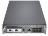
Installing a Hard-Disk Drive Warning To reduce the risk of fire, electric shock, and injury, disconnect the power cord and any cables that connect to the appliance or gateway before you open the chassis and expose internal components. Even though the power switch is turned off, power is still present inside the appliance or gateway. 4. Loosen the two front panel retaining screws. STATUS POWER FAULT IP290 1 3 5 1000BaseT LINK ACT SLOT 1 LINK ACT RESET AUX CONSOLE 2 4 6 00565 Chassis tray assembly retaining screws 5. Slide the chassis tray assembly forward, and completely remove the chassis to expose the motherboard components. Note If you are unable to slide out the chassis tray assembly, you might need to remove the shipping screw from the back of the appliance. For details, see Figure 5 on page 24. 1000BaseT LINK ACT SLOT 1 STATUS LINK ACT POWER FAULT AUX RESET CONSOLE 1 IP290 3 5 2 4 6 6. Place the chassis tray assembly on a table top. Nokia IP290 Security Platform Installation Guide 00563 55
-
 1
1 -
2
-
3
-
4
-
5
-
6
-
7
-
8
-
9
-
10
-
11
-
12
-
13
-
14
-
15
-
16
-
17
-
18
-
19
-
20
-
21
-
22
-
23
-
24
-
25
-
26
-
27
-
28
-
29
-
30
-
31
-
32
-
33
-
34
-
35
-
36
-
37
-
38
-
39
-
40
-
41
-
42
-
43
-
44
-
45
-
46
-
47
-
48
-
49
-
 50
50 -
 51
51 -
 52
52 -
 53
53 -
 54
54 -
 55
55 -
 56
56 -
 57
57 -
 58
58 -
 59
59 -
 60
60 -
61
-
62
-
63
-
64
-
65
-
66
-
67
-
68
-
69
-
70
-
71
-
72
-
73
-
74
-
75
-
76
-
77
-
78
-
79
-
80
-
81
 |
 |
