Nokia IP290 Installation Guide - Page 50
From beneath the chassis tray assembly, screw in the bezel retaining screws., on the back of the NIC.
 |
View all Nokia IP290 manuals
Add to My Manuals
Save this manual to your list of manuals |
Page 50 highlights
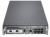
5 Installing and Replacing Network Interface Cards 9. From the top of the chassis tray assembly, screw the NIC retaining screws into the standoffs on the back of the NIC. 1000BaseT LINK ACT SLOT 1 STATUS POWER LINK ACT FAULT AUX RESET CONSOLE 1 IP290 3 5 2 4 6 00571 10. From beneath the chassis tray assembly, screw in the bezel retaining screws. 11. Slide the chassis tray assembly back into the appliance. 50 Nokia IP290 Security Platform Installation Guide
-
 1
1 -
2
-
3
-
4
-
5
-
6
-
7
-
8
-
9
-
10
-
11
-
12
-
13
-
14
-
15
-
16
-
17
-
18
-
19
-
20
-
21
-
22
-
23
-
24
-
25
-
26
-
27
-
28
-
29
-
30
-
31
-
32
-
33
-
34
-
35
-
36
-
37
-
38
-
39
-
40
-
41
-
42
-
43
-
44
-
 45
45 -
 46
46 -
 47
47 -
 48
48 -
 49
49 -
 50
50 -
 51
51 -
 52
52 -
 53
53 -
 54
54 -
 55
55 -
56
-
57
-
58
-
59
-
60
-
61
-
62
-
63
-
64
-
65
-
66
-
67
-
68
-
69
-
70
-
71
-
72
-
73
-
74
-
75
-
76
-
77
-
78
-
79
-
80
-
81
 |
 |

5
Installing and Replacing Network Interface Cards
50
Nokia IP290 Security Platform Installation Guide
9.
From the top of the chassis tray assembly, screw the NIC retaining screws into the standoffs
on the back of the NIC.
10.
From beneath the chassis tray assembly, screw in the bezel retaining screws.
11.
Slide the chassis tray assembly back into the appliance.
00571
IP290
STATUS
SLOT 1
AUX
RESET
1
3
5
2
4
6
CONSOLE
POWER
FAULT
1000BaseT
LINK
ACT
LINK
ACT