Nokia IP290 Installation Guide - Page 28
To remove the appliance, use a screwdriver to turn the locking latch
 |
View all Nokia IP290 manuals
Add to My Manuals
Save this manual to your list of manuals |
Page 28 highlights
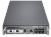
2 Installing the Nokia IP290 Appliance 3. Slide one or two appliances into the shell openings. 1000BaseT LINK ACT SLOT 1 STATUS LINK ACT POWER FAULT AUX RESET CONSOLE 1 IP290 3 5 2 4 6 Filler panel 00563 4. Secure each appliance to the shell by using a screwdriver to turn the locking latch clockwise until you cannot turn it with light force. To remove the appliance, use a screwdriver to turn the locking latch counterclockwise until you cannot turn it with light force. To secure the appliance To release the appliance 3 5 4 6 3 5 4 6 00562 28 Nokia IP290 Security Platform Installation Guide
-
 1
1 -
2
-
3
-
4
-
5
-
6
-
7
-
8
-
9
-
10
-
11
-
12
-
13
-
14
-
15
-
16
-
17
-
18
-
19
-
20
-
21
-
22
-
 23
23 -
 24
24 -
 25
25 -
 26
26 -
 27
27 -
 28
28 -
 29
29 -
 30
30 -
 31
31 -
 32
32 -
 33
33 -
34
-
35
-
36
-
37
-
38
-
39
-
40
-
41
-
42
-
43
-
44
-
45
-
46
-
47
-
48
-
49
-
50
-
51
-
52
-
53
-
54
-
55
-
56
-
57
-
58
-
59
-
60
-
61
-
62
-
63
-
64
-
65
-
66
-
67
-
68
-
69
-
70
-
71
-
72
-
73
-
74
-
75
-
76
-
77
-
78
-
79
-
80
-
81
 |
 |

2
Installing the Nokia IP290 Appliance
28
Nokia IP290 Security Platform Installation Guide
3.
Slide one or two appliances into the shell openings.
4.
Secure each appliance to the shell by using a screwdriver to turn the locking latch
clockwise
until you cannot turn it with light force.
To remove the appliance, use a screwdriver to turn the locking latch
counterclockwise
until
you cannot turn it with light force.
00563
IP290
STATUS
AUX
1
3
5
2
4
6
CONSOLE
POWER
FAULT
SLOT 1
Filler panel
3
5
4
6
3
5
4
6
00562
To secure the appliance
To release the appliance