Nokia IP290 Installation Guide - Page 49
Insert the NIC bezel into the front panel.
 |
View all Nokia IP290 manuals
Add to My Manuals
Save this manual to your list of manuals |
Page 49 highlights
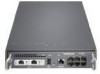
Installing NICs 8. Insert the new NIC. a. Insert the NIC bezel into the front panel. b. Gently push the back of the NIC down toward the chassis tray assembly. 1000BaseT LINK ACT LINK ACT SLOT 1 STATUS POWER FAULT AUX RESET CONSOLE 1 IP290 3 5 2 4 6 00572 Make sure that the NIC edge is completely seated into the connectors on the chassis tray assembly. Nokia IP290 Security Platform Installation Guide 49
-
 1
1 -
2
-
3
-
4
-
5
-
6
-
7
-
8
-
9
-
10
-
11
-
12
-
13
-
14
-
15
-
16
-
17
-
18
-
19
-
20
-
21
-
22
-
23
-
24
-
25
-
26
-
27
-
28
-
29
-
30
-
31
-
32
-
33
-
34
-
35
-
36
-
37
-
38
-
39
-
40
-
41
-
42
-
43
-
 44
44 -
 45
45 -
 46
46 -
 47
47 -
 48
48 -
 49
49 -
 50
50 -
 51
51 -
 52
52 -
 53
53 -
 54
54 -
55
-
56
-
57
-
58
-
59
-
60
-
61
-
62
-
63
-
64
-
65
-
66
-
67
-
68
-
69
-
70
-
71
-
72
-
73
-
74
-
75
-
76
-
77
-
78
-
79
-
80
-
81
 |
 |

Installing NICs
Nokia IP290 Security Platform Installation Guide
49
8.
Insert the new NIC.
a.
Insert the NIC bezel into the front panel.
b.
Gently push the back of the NIC down toward the chassis tray assembly.
Make sure that the NIC edge is completely seated into the connectors on the chassis tray
assembly.
00572
IP290
STATUS
SLOT 1
AUX
RESET
1
3
5
2
4
6
CONSOLE
POWER
FAULT
LINK
ACT
LINK
ACT
1000BaseT